166
WSG-1068 IGNITION SYSTEM
Overview
The Ignition System is designed to ignite the
compressed air/fuel mixture in an internal combustion
engine by a high voltage spark from an ignition coil. The
ignition system also provides engine timing information
to the GCP for proper engine operation and misfire
detection.
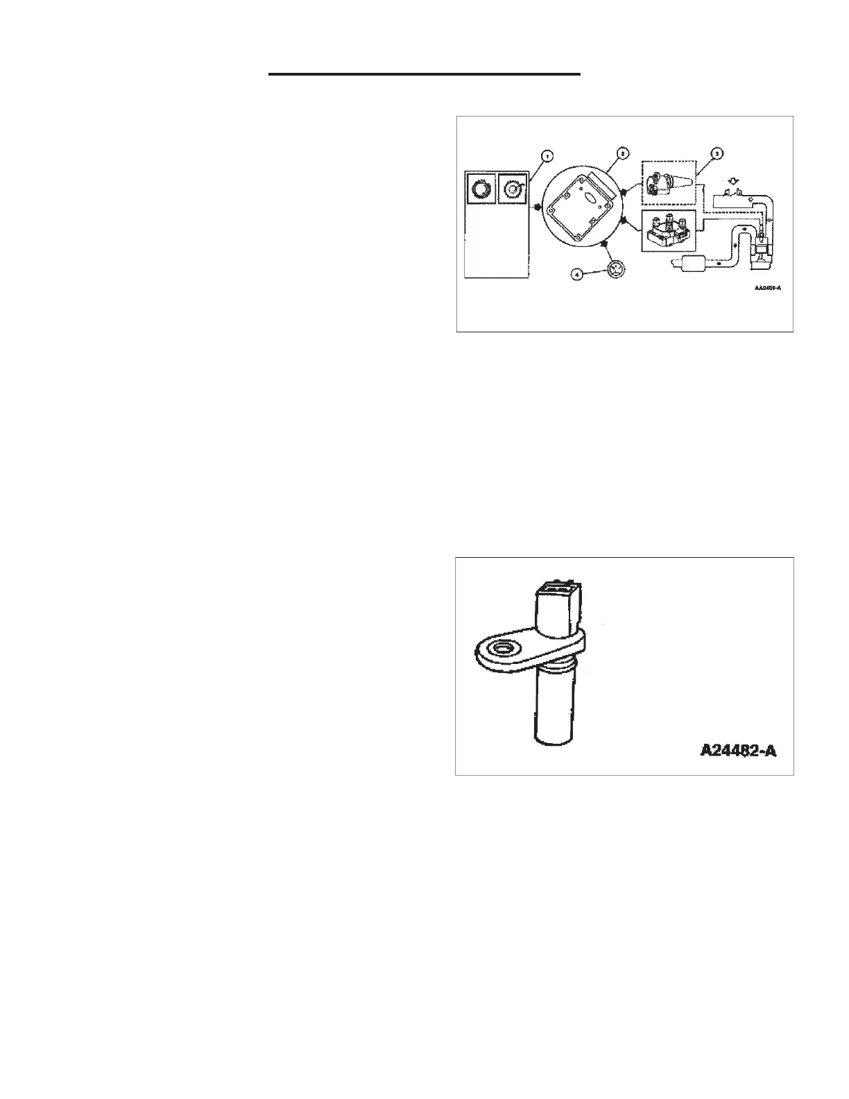
Electronic Ignition System
The Coil On Plug (COP) EI System uses a separate coil
per spark plug and each coil is mounted directly onto the
plug. The COP EI System eliminates the need for spark
plug wires but does require input from the camshaft
position (CMP) sensor. Operation of the components are
as follows:
1. Note: Electronic Ignition engine timing is entirely
controlled by the GCP. Electronic Ignition engine
timing is NOT adjustable. Do not attempt to
check base timing. You will receive false
readings.
2. The GCP uses the CMP sensor not shown on
COP EI Systems to identify top dead center of
compression of cylinder 1 to synchronize the
firing of the individual coils.
3. The GCP acts as an electronic switch to ground
in the coil primary circuit. When the switch is
closed, battery positive voltage (B+) applied to
the coil primary circuit builds a magnetic field
around the primary coil. When the switch opens,
the power is interrupted and the primary field
collapses inducing the high voltage in the
secondary coil windings and the spark plug is
fired. A kickback voltage spike occurs when the
primary field collapses.
4. The GCP processes the CKP signal and uses it
to drive the tachometer as the Clean Tach Out
(CTO) signal.
Starting RPM
The program strategy requires the engine to obtain a
minimum of 100-140 RPM before the GCP will allow
ignition spark to be generated. Any failure with an
auxiliary system can cause excessive engine crank
(load) force, which may cause the engine too not reach
the required starting RPM. Perform a thorough
inspection of all auxiliary systems and components,
inspect for binding hydraulic pumps and misalignment of
drive systems.
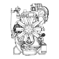
Camshaft Position Sensor
The Camshaft Position (CMP) Sensor detects the
position of the camshaft. The CMP Sensor identifies
when piston #1 is on its compression stroke.
The CMP Sensor is a magnetic transducer mounted on
the engine front cover adjacent to the camshaft. By
monitoring a target on the camshaft sprocket, the CMP
sensor identifies cylinder one to the GCP. The COP EI
system uses this information to synchronize the firing of
the individual coils.