Technical Manual &
Cabling Instructions
Page 20 / MAN000596
AI/DI
Epec Oy reserves all rights for improvements without prior notice
Epec Oy
Tiedekatu 6
FIN-60320 Seinäjoki
Postal address
PL/P.O.Box 194
FIN-60101 Seinäjoki,
Finland
Phone
+358-(0)20-7608 111
Fax
+358-(0)20-7608 110
Internet
www.epec.fi
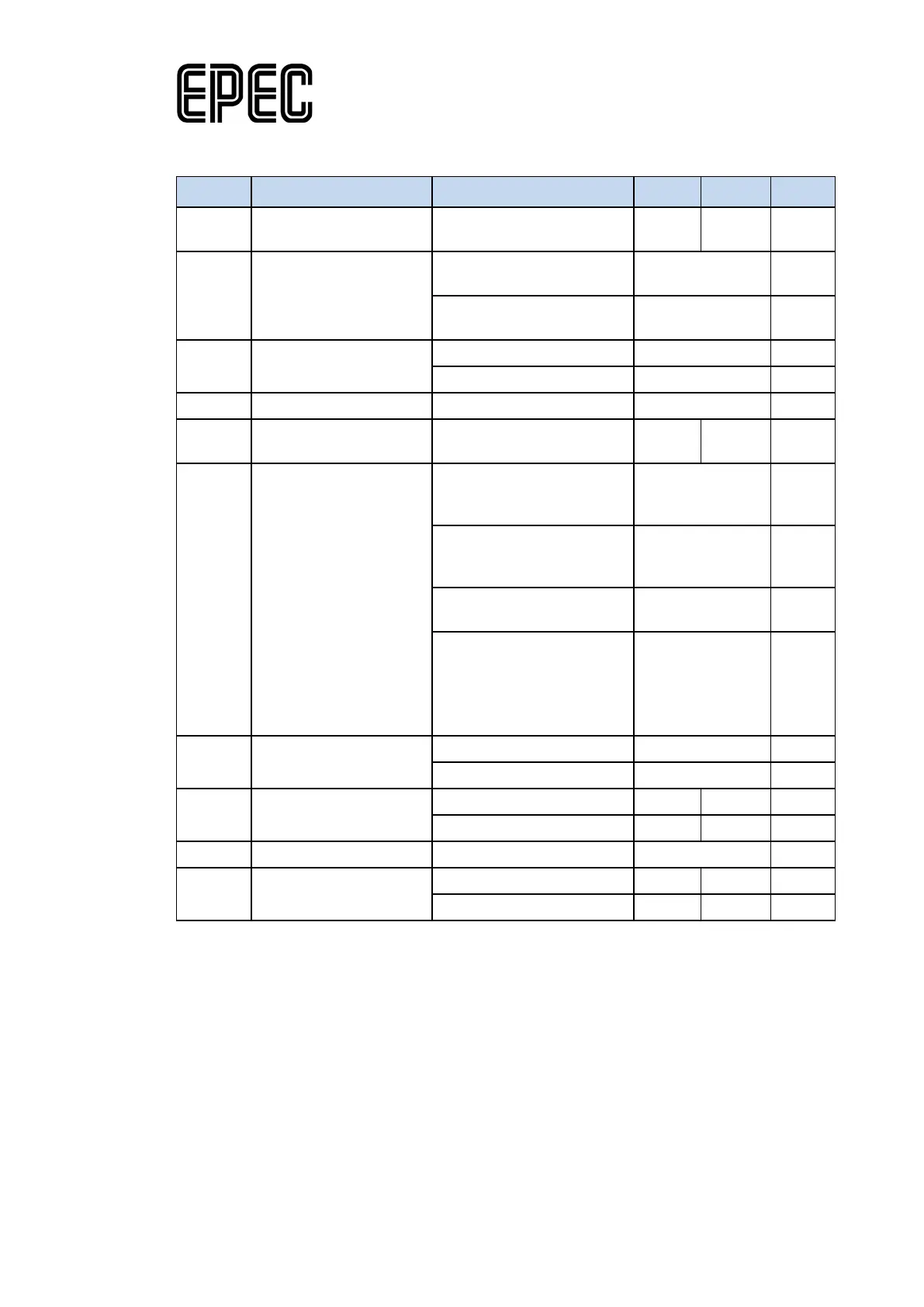
Electrical characteristics
Conditions
V
I
Input Voltage measuring
range
Voltage mode 0 5,5 V
Overvoltage Detection
Threshold
Protection mode not active
(Note 5)
typ. 7,2 V
Protection mode active
typ. 5,6 V
Scaling factor
PU
I
I
range
Current mode 0 22 mA
R
I
Input Resistance
Voltage mode, pull-up
resistor not selected
(referenced to GND)
typ. 70 kΩ
Voltage mode, pull-up
resistor selected
(referenced to + 5 V)
typ. 2200 Ω
Current mode (referenced
typ. 220 Ω
Overvoltage protection
mode,
V
I
> Overvoltage detection
threshold
typ. 9,6 kΩ
BW
Input Low Pass Filter
Bandwidth
I
E
Input Error
I
V
I-range
Input Voltage Range
Note 1: Temperature-dependent.
Note 2: Exceeding the max value might cause damage to input.
Note 3: 2nd order low pass filter
Note 4: HW multiplies the measurement by 10/11. The effect is compensated in 6107Int.library
(the measurement is multiplied by 11/10), so the measurement is automatically accurate when
using Epec programming libraries. For more information about conversions, refer to Epec
Programming and Libraries manual.
Note 5: When protection mode is active the measurement circuit is disconnected from the input.