Technical Manual &
Cabling Instructions
Page 67 / MAN000596
Mechanics and
Cabling
Epec Oy reserves all rights for improvements without prior notice
Epec Oy
Tiedekatu 6
FIN-60320 Seinäjoki
Postal address
PL/P.O.Box 194
FIN-60101 Seinäjoki,
Finland
Phone
+358-(0)20-7608 111
Fax
+358-(0)20-7608 110
Internet
www.epec.fi
15.4.3 I/O Cabling
Closed circuit loops are always recommended and mandatory when you are
using DO or PWM pin as an input.
To ensure correct measurement, reserve separate GND pin(s) for
AI pin(s) and don't use it/them for any other purposes. See cabling
• The cabling for encoders etc. is in many cases supplied together with them.
• In many cases, very simple basic cable may be used, e.g. automobile R2 cable (0,5 or 1,0)
by NK Cables.
• Dimensions of the cable should be appropriate for AMP contacts (so that crimping is
possible).
• Refer to AMPSEAL table (in section Accessories and Ordering Codes
) for dimensions.
• Take extra care for protecting the cables against physical wear and damage.
• Only one wire can be connected to one AMPSEAL connector pin. However, if more than
one wire has to be connected to one connector pin, it has to be connected by branch
wiring.
• Some voltage inputs use relatively low voltages.
• Consider using shielded cables for these encoders etc. especially for longer distances
to increase safety
• Using shielded cable is recommended also in joystick connections.
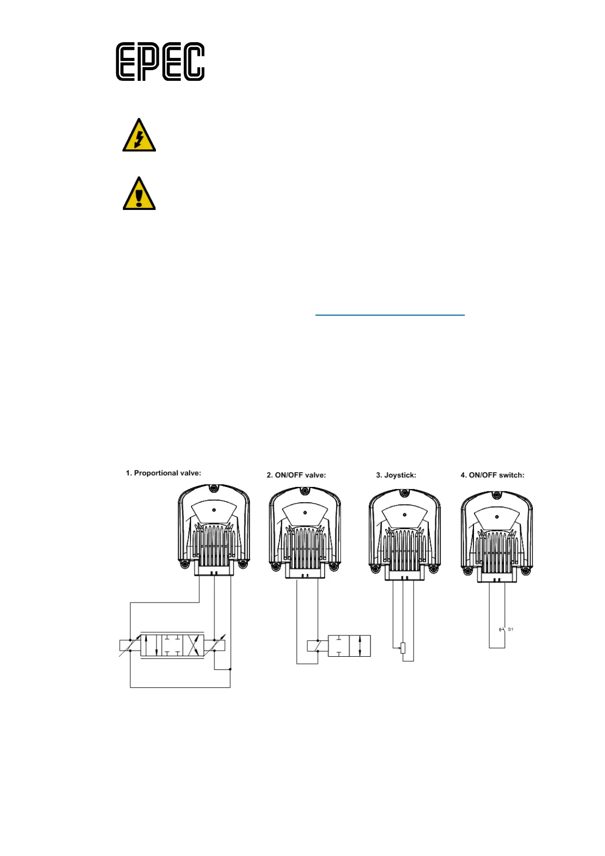
The following figure describes four different ways to connect closed circuit loop through the
control unit: