Technical Manual &
Cabling Instructions
Page 32 / MAN000596
Interfaces
Epec Oy reserves all rights for improvements without prior notice
Epec Oy
Tiedekatu 6
FIN-60320 Seinäjoki
Postal address
PL/P.O.Box 194
FIN-60101 Seinäjoki,
Finland
Phone
+358-(0)20-7608 111
Fax
+358-(0)20-7608 110
Internet
www.epec.fi
12.5 Camera
This manual describes the full hardware version. Some of the features are
optional and not implemented in all hardware versions.
+12 V from X5 connector for cameras is not allowed when GSM/GPS is in use.
max 2
PAL (NTSC on request)
Twisted pair or coaxial cable
0,8 A (2 x 400 mA, internal automatic fuse)
Ordering camera cables and cameras:
See section Accessories and Ordering
Codes
Related programming libraries:
6000Multimedia.library
(For more information, see Epec
Programming and Libraries manual)
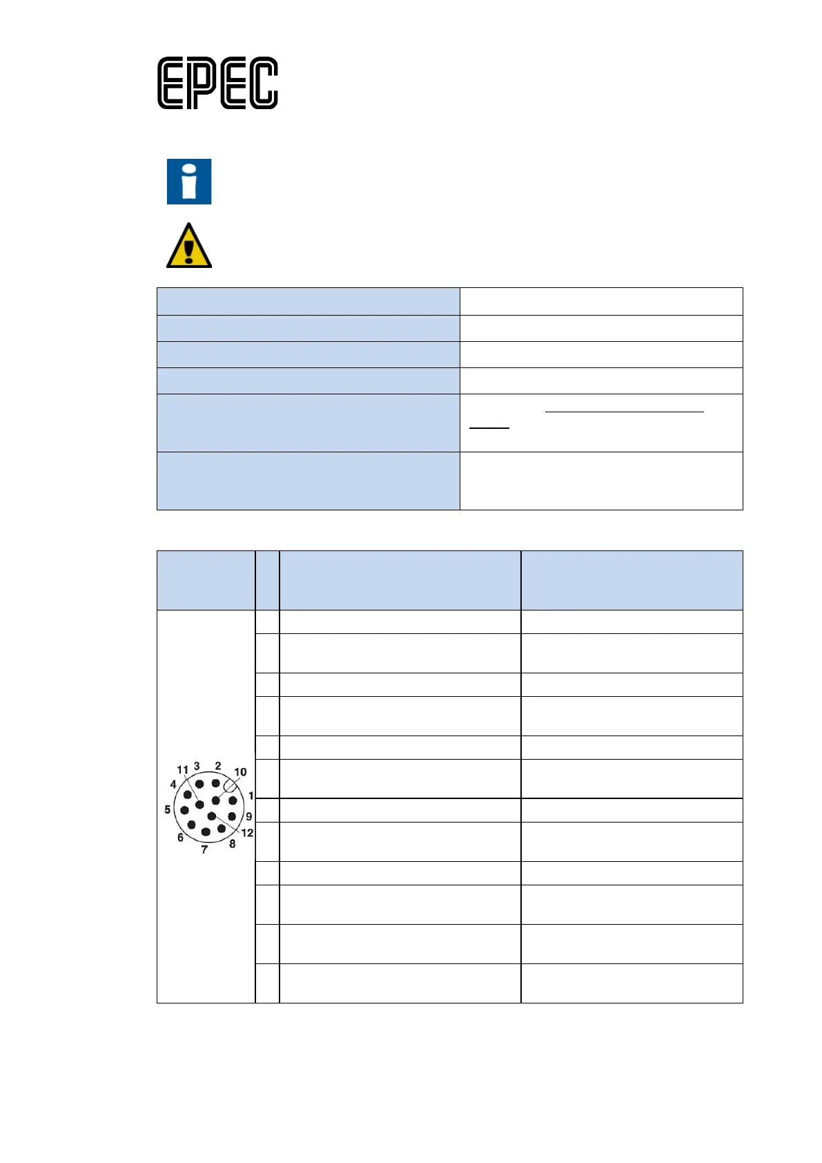
X5, M12 connector (12 pin MALE, 2xcamera)
Signal
(default configuration for composite
video)
(optional hw configuration for s
video)
1
- CAMERA1_CHROMA_INPUT
2
-
LD
3
CAMERA1_COMPOSITE_INPUT CAMERA1_LUMA_INPUT
4
CAMERA1_COMPOSITE_GND/SHI
ELD
CAMERA1_LUMA_GND/SHIELD
5
- CAMERA2_CHROMA_INPUT
6
- CAMERA2_CHROMA_GND/SHIE
LD
7
CAMERA2_COMPOSITE_INPUT CAMERA2_LUMA_INPUT
8
CAMERA2_COMPOSITE_GND/SHI
ELD
CAMERA2_LUMA_GND/SHIELD
1
0
+12 V (CAMERA2)* +12 V (CAMERA2)*
1
1
GND (CAMERA1) GND (CAMERA1)
1
GND (CAMERA2) GND (CAMERA2)
* +12 V for cameras is not allowed when GSM/GPS is in use.