Technical Manual &
Cabling Instructions
Page 28 / MAN000596
Interfaces
Epec Oy reserves all rights for improvements without prior notice
Epec Oy
Tiedekatu 6
FIN-60320 Seinäjoki
Postal address
PL/P.O.Box 194
FIN-60101 Seinäjoki,
Finland
Phone
+358-(0)20-7608 111
Fax
+358-(0)20-7608 110
Internet
www.epec.fi
12 INTERFACES
12.1 CAN Bus
2
All interfaces support bit rates 50, 125, 250, 500,1000 kbit/s
• Implementations of higher layer protocols are user
programmable. Epec provides implementations for
CANopen and SAE J1939 as PLCopen libraries
• The physical interface of CAN is according to ISO 11898
and CAN 2.0B protocol
• 11-bit and 29-bit message receive and transmit are
supported
• Transmitting of remote frames is supported in all CAN
interfaces
See section CAN Bus Cabling
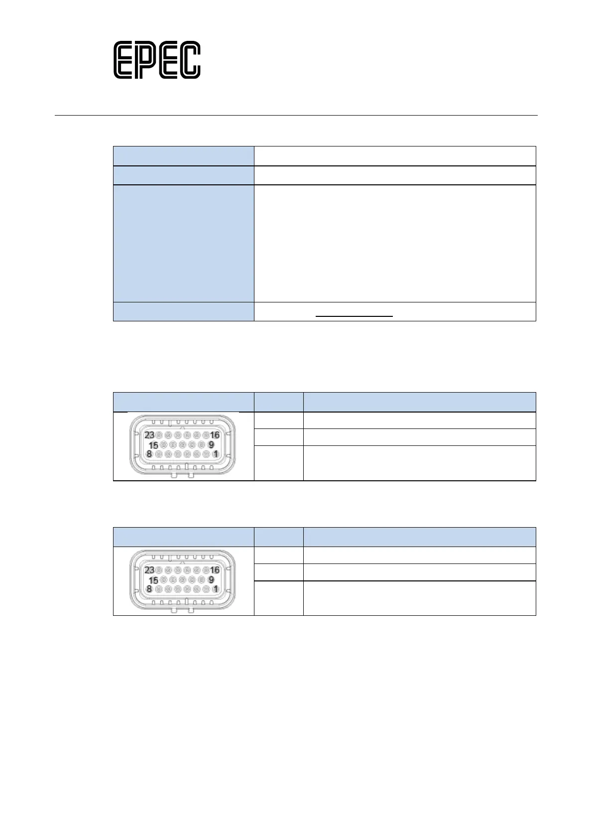
12.1.1 CAN bus connection pins
The CAN1 communication pins are located in the control unit's AMP23 (X1) connector as
follows:
Picture
7 CAN1 L
8 CAN1 H
10 GND (DATA GROUND)
The CAN2 communication pins are located in the control unit's AMP23 (X1) connector as
follows:
Picture
13 CAN2 L
14 CAN2 H
10 GND (DATA GROUND)