Technical Manual &
Cabling Instructions
Page 73 / MAN000596
Mechanics and
Cabling
Epec Oy reserves all rights for improvements without prior notice
Epec Oy
Tiedekatu 6
FIN-60320 Seinäjoki
Postal address
PL/P.O.Box 194
FIN-60101 Seinäjoki,
Finland
Phone
+358-(0)20-7608 111
Fax
+358-(0)20-7608 110
Internet
www.epec.fi
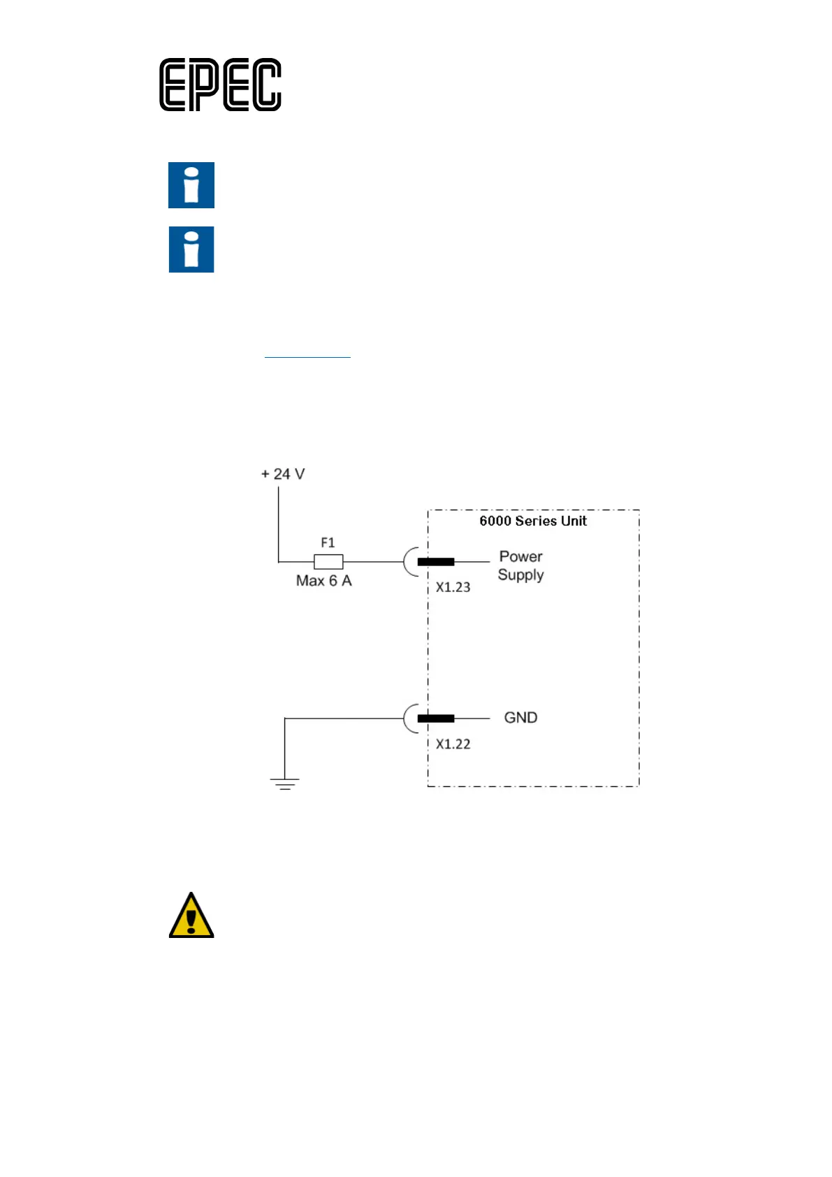
15.4.7 Power Supply Cabling
The maximum continuous current per pin is 6 A.
The power for sensors, encoders and other equipment should be supplied from
the very same unit that the equipment is connected to, to ensure the best
performance of the system.
No external power (or ground) connections are
• The nominal operating voltage for Epec control units is 12 and 24 VDC. The full operating
range is8,4…36 VDC
• See section Power Supply
for accurate pin allocation of the connectors
• Single point grounding should be used for power supply for all the control units
• The type and parameters of the power supply fuse should be selected depending on the
machine type and product use case
Power supply’s wiring example:
15.4.8 Emergency Stop
In all European Community countries, the emergency stop should be
implemented in accordance with standard EN ISO 13850, which complies to the
EC Machinery directive 2006/42/EC. In other countries, the emergency stop
should be implemented according to local standards and/or to local legislation.