Technical Manual &
Cabling Instructions
Page 64 / MAN000596
Mechanics and
Cabling
Epec Oy reserves all rights for improvements without prior notice
Epec Oy
Tiedekatu 6
FIN-60320 Seinäjoki
Postal address
PL/P.O.Box 194
FIN-60101 Seinäjoki,
Finland
Phone
+358-(0)20-7608 111
Fax
+358-(0)20-7608 110
Internet
www.epec.fi
15.4.2 CAN Bus Cabling
The CAN bus cable is the neural backbone of the whole system and should be
designed and constructed with extra care.
• For information about the CAN bus lengths and baud rates, refer to section
System
Topologies.
Cable
• It is recommended to use high quality and twisted (approx. 1 round / 1 inch) CAN bus
cable.
• Normal UTP (Unshielded Twisted Pairs) cable is well suited for distances under
approximately 10 meters.
• In longer distances, and especially if there is possibility for electromagnetic interference, it
is highly recommended to use shielded and twisted cable for CAN bus, also for shorter
distances.
• To avoid electromagnetic interference (EMI), locate the bus cable as far away from high-
current carrying cables as possible. Generally, the amount of the connections and
connectors should be minimized to maximize security; also all connections should be done
carefully.
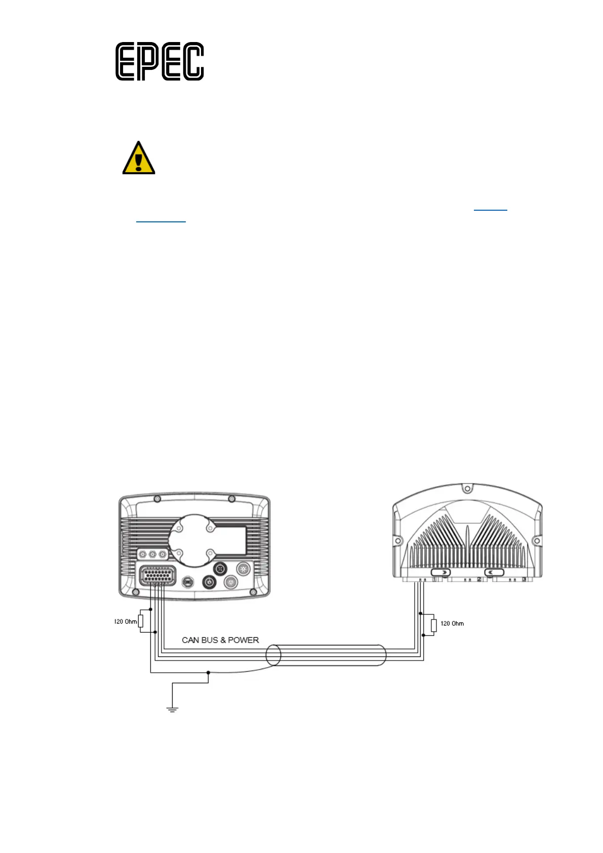
• The shield grounding must be done only in one end of the cable
Cable shield
Connection example when there is a GND pin (X1.22) available in the control unit: