Technical Manual &
Cabling Instructions
Page 70 / MAN000596
Mechanics and
Cabling
Epec Oy reserves all rights for improvements without prior notice
Epec Oy
Tiedekatu 6
FIN-60320 Seinäjoki
Postal address
PL/P.O.Box 194
FIN-60101 Seinäjoki,
Finland
Phone
+358-(0)20-7608 111
Fax
+358-(0)20-7608 110
Internet
www.epec.fi
Ethernet cable connection with Epec 6000 series unit:
connector
(front)
(Ethern
et)
pin
(Ethern
et 2)
male
pin
air
(according
standard)
connector
(front)
6
(rxd1+)
1
(rxd2+
3
(rxd
3 White/gre
en
5
(txd1+)
2
(txd2+
1
(txd
2 White/ora
nge
4
(rxd1-)
7
(rxd2-)
6
(rxd
3 Green
8
(txd1-)
3
(txd2-)
2
(txd-
2 Orange
7 4 White/bro
wn
8 4 Brown
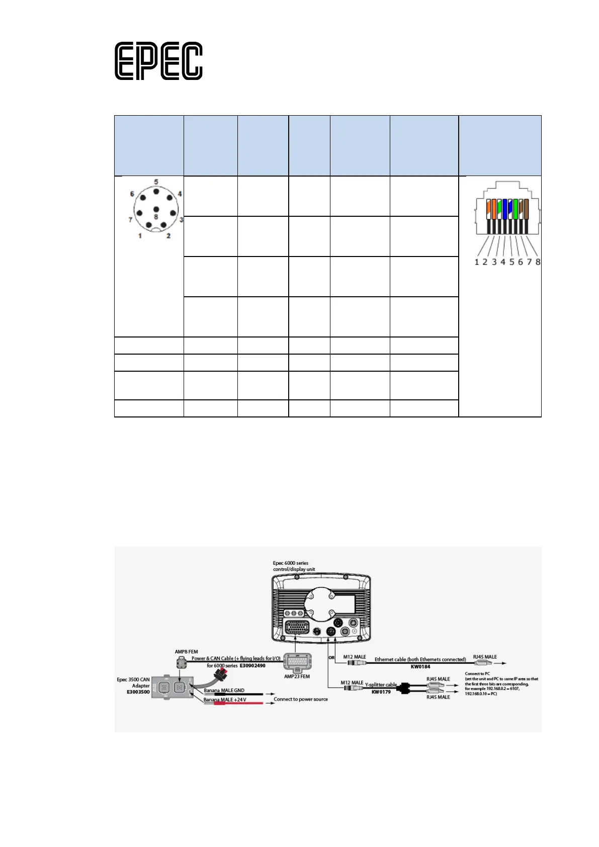
15.4.4.2 Ethernet cabling for system developers
The following figure describes a cabling example for Ethernet communication between Epec
control units and a PC.
Ordering codes for the needed hardware are included in the figure.
To check 6000 series unit's IP addresses, use ApplicationLoader (device software). For more
information, see Epec Programming & Libraries Manual: Programming > Programming 6000
Series Units > Configuring Ethernet and DNS Settings (available from Epec's Extranet).