EPSON Stylus PHOTO 2100/2200 Revision B
DISASSEMBLY AND ASSEMBLY Disassembly 161
4.2.12 Removing the Sensors
4.2.12.1 Removing the PG Sensor and Release Sensor
1. Remove the Rear Housing. (Refer to 4.2.1.2.)
2. Disconnect the Connector Cables of the PG Sensor and Release Sensor from the
Connectors of the PG Sensor and Release Sensor.
3. Release the two hooks that secure each of the PG Sensor and Release Sensor, and
remove the PG Sensor and Release Sensor.
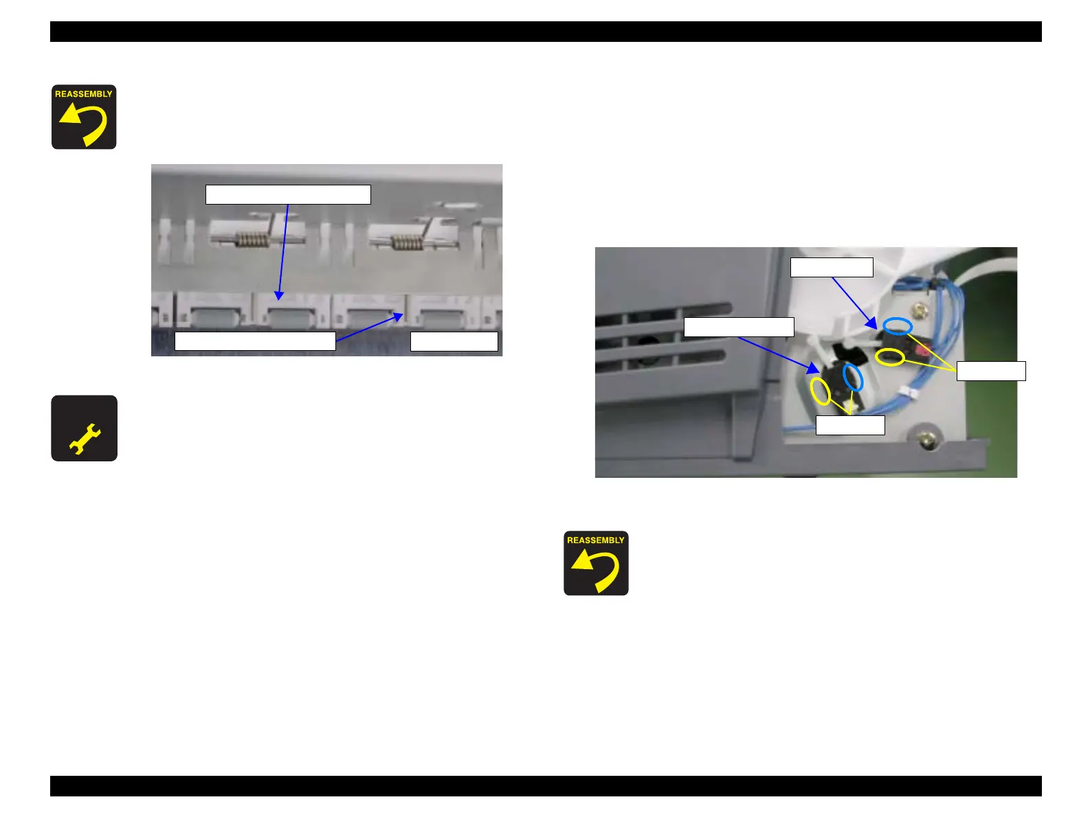
Figure 4-91. Removing the PG Sensor and Release Sensor
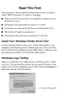
" When reinstalling the Torsion Springs 117.9, make sure that the
Torsion Springs 117.9 are placed correctly in the spring setting
positions of the Driven Roller Assembly (printer front).
Refer to Figure 4-90, "Torsion Spring 117.9 Setting Position".
Figure 4-90. Torsion Spring 117.9 Setting Position
A D J U S T M E N T
R E Q U I R E D
" After changing the following parts for new ones, always apply
grease G-26 in the specified positions.
• Release Lever Shaft:
Refer to Chapter 6, Figure 6-11, "Lubrication Point 13".
• Click Lever:
Refer to Chapter 6, Figure 6-16, "Lubrication Point 18".
• Release Lever, Release Connect Lever, Intermittent Gear
24, 30:
Refer to Chapter 6, Figure 6-17, "Lubrication Point 19".
Torsion Spring 117.9
Driven Roller Assembly
Top center
When reinstalling the PG Sensor and Release Sensor, locate the
PG Sensor Connector Cable end, which is read, in the top right
position, and the Release Sensor Connector Cable end, which is
yellow, in the bottom left position.
Refer to Figure 4-91, "Removing the PG Sensor and Release
Sensor".
Hooks
Hooks
Release Sensor
PG Sensor

 Loading...