EPSON Stylus PHOTO 2100/2200 Revision B
OPERATING PRINCIPLES Electrical Circuitry Operating Principles 67
2.3.1 Power Supply Circuit Operating Principle
The power supply circuit board of this product is the C387 PSB/PSE. The basic structure of
the circuit uses the RCC switching regulator method and +42VDC and +5DVC are
supplied to the printer mechanism and control boards.
The following indicates the applications of the voltages generated in this power supply
circuit.
Note: +5VDC applies to only the parts and areas in the above table. 3.3V/2.5V drive
components are used as most logic chips (CPU, P-ROM, SDRAM) on the C387MAIN
board. Hence, they do not operate at the +5VDC regulator DC generated by the
C387PSB/PSE. Each 3.3V/2.5V drive chip operates at 3.3V/2.5V reduced by the 3.3V/
2.5V generating regulator on the MAIN board circuit.
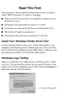
The following is the block diagram of the power supply circuit.
Figure 2-18. Power Supply Circuit Block Diagram
Table 2-15. Supplied Power
Voltage Applications
+42 +/- 2VDC
Rated output current: 0.5A
• CR motor
• ASF/Pump motor
• PF motor
• Head drive voltage
+5 +/- 0.25VDC
Rated output current: 0.6A
• Logic sensor circuit
•Panel LED
• Nozzle selection circuit (above Printhead)
• Interface control circuit
• Ink cartridge sensor
• PE sensor
• ASF sensor
• Cutter HP sensors (left, right)

 Loading...