EPSON Stylus PHOTO 2100/2200 Revision B
DISASSEMBLY AND ASSEMBLY Disassembly 158
4.2.10 Removing the Ink System Unit
1. Remove the Printer Mechanism. (Refer to 4.2.1.4.)
2. Move the Carriage Unit to the center.
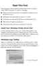
3. Remove the four screws 6) C.B.S 3
×6 (9±1kgf.cm) that secure the Ink System
Unit.
Figure 4-83. Removing the Ink System Unit
4. Remove the three hooks, which secure the Cap Unit, from the I/S Frame, remove
the one projection on the Head Cleaner side from the Cap Unit, remove the Ink
Tube connection from the Pump Tube, and remove the Cap Unit.
Figure 4-84. Removing the Cap Unit
C H E C K
P O I N T
The Ink System Unit consists of the Cap Unit, Pump Unit and
Head Cleaner.
Fit the screws 6) C.B.S 3×6 in the order shown in Figure 4-83.
C.B.S 3x6
C.B.S 3×6
Ink System Unit
2
3
1
4
C A U T I O N
When removing the Ink Tube from the Pump Tube, be careful of
ink leakage.
Figure 4-84, "Removing the Cap Unit".
Hooks
Projection
Cap Unit
I/S Frame
Ink Tube
Ink Tube
connection
Pump Tube

 Loading...