EPSON Stylus PHOTO 2100/2200 Revision B
DISASSEMBLY AND ASSEMBLY Disassembly 159
4.2.11 Removing the Release Lever Shaft
1. Remove the Printer Mechanism. (Refer to 4.2.1.4.)
2. Remove the ASF Unit. (Refer to Steps 2 to 4 in 4.2.4.)
3. Move the Release Lever to the thick paper printing position, and remove the PG
Change Spring Link from the PG Change Spring Lever.
Figure 4-85. Removing the PG Change Spring Link
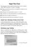
4. Before removing the PG Change Spring Lever and Release Connect Lever,
remove the C Ring, and then remove the PG Change Spring Lever, Intermittent
Gear 24, 30 and Release Connect Lever in this order.
Figure 4-86. Removing the Gears
C H E C K
P O I N T
When you remove the two screws that secure the Cap Unit and
carry out Step 4, you can remove the Cap Unit without removing
the Ink System Unit.
Refer to Figure 4-83, "Removing the Ink System Unit" and Figure
4-84, "Removing the Cap Unit".
PG Change
Spring Lever
PG Change
Spring Link
Release Connect Lever
C Ring
Intermitte
nt Gear
24,30
C Ring
Parallel Pin
Printer right side

 Loading...