EPSON Stylus PHOTO 2100/2200 Revision B
DISASSEMBLY AND ASSEMBLY Disassembly 182
4.2.18 Disassembling the Cutter Unit
4.2.18.1 Removing the Cutter Sensor
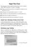
1. Remove the two screws 15) C.B.S 3×8 (9±1kgf.cm), two screws 6) C.B.S 3×6
(9±1kgf.cm) and two screws (T.B.D) that secure the Cutter Housing.
2. Release the three hooks located on the Cutter Unit bottom.
Figure 4-138. Screws That Secure the Cutter Housing
" When reinstalling the PF Roller Support, hitch the two upper
hooks on the projections of the Under Frame, and insert the two
lower hooks into the notches.
Refer to Figure 4-137, "Removing the PF Roller Support".
" Place the Under Driven Roller on the joggle of the PF Roller
Support in advance.
Refer to Figure 4-137, "Removing the PF Roller Support".
C.B.S 3x8
C.B.S 3x6
Cutter
Housing
Screws T.B.D
Hooks

 Loading...