EPSON Stylus PHOTO 2100/2200 Revision B
DISASSEMBLY AND ASSEMBLY Disassembly 149
4.2.8 Removing the Carriage Guide Shaft B
1. Remove the Printer Mechanism. (Refer to 4.2.1.4.)
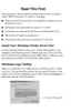
2. Slightly slide the Carriage Unit to the left as viewed from the printer front, move
the Release Lever to the thick paper print position, and remove the PG Change
Spring Link from the PG Change Lever.
Figure 4-65. Removing the PG Change Spring Link
3. Turn the PG Change Bush and PG Change Lever clockwise as seen from the
printer right side until the shape of the cutout in the right end of the PG Change
Link matches that of the cutout in the PG Change Lever. Then, pull the PG Change
Lever to the front and remove the cutout of the PG Change Link.
C H E C K
P O I N T
" The ASP structure of the Head FFC Guide is the Head FFC
Guide, Sponge, Ferrite Core and double-faced tape. When
changing the Head FFC Guide, reinstall it after making sure that
the Sponge and Ferrite Core are fitted in the correct positions.
Leave a 0 to 2mm clearance above the Sponge and Frame.
Figure 4-64. Normal Position of Ferrite Core
Ferrite Core
Sponge
PG Change Lever
PG Change Spring Link

 Loading...