EPSON Stylus PHOTO 2100/2200 Revision B
APPENDIX Connector Summary 227
7.1 Connector Summary
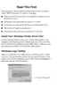
This section shows the connections between the main components of the printer.
Figure 7-1. Connection of the Major Components
7.1.1 Connectors and Pin Layouts
See the following tables for the connector summary for the C387 MAIN board and
each connector's pin alignment.
Table 7-1. Connector Summary for C387 MAIN
Connector Function Ref.
CN1 Release sensor Table 7-2
CN2 Cutter unit Table 7-3
CN4 PE sensor Table 7-4
CN8 ASF/Pump motor Table 7-5
CN9 PF encoder Table 7-6
CN10
Printhead (including CR encoder input and
head temperature)
Table 7-7
CN11
Printhead
(including CSIC transmissions)
Table 7-8
CN12 ASF sensor Table 7-9
CN13 PG sensor Table 7-10
CN14 Panel board Table 7-11
CN15 Power supply board Table 7-12
CN16 PF motor Table 7-13
CN17 CR motor Table 7-14
CN18 CD-R sensor Table 7-15

 Loading...