SC-S30600 Series Revision B
DISASSEMBLY & ASSEMBLY Disassembly and Assembly Procedure 191
Confidential
3.4.9.5 Tension Bar Upper Sensor / Tension Bar Lower Sensor
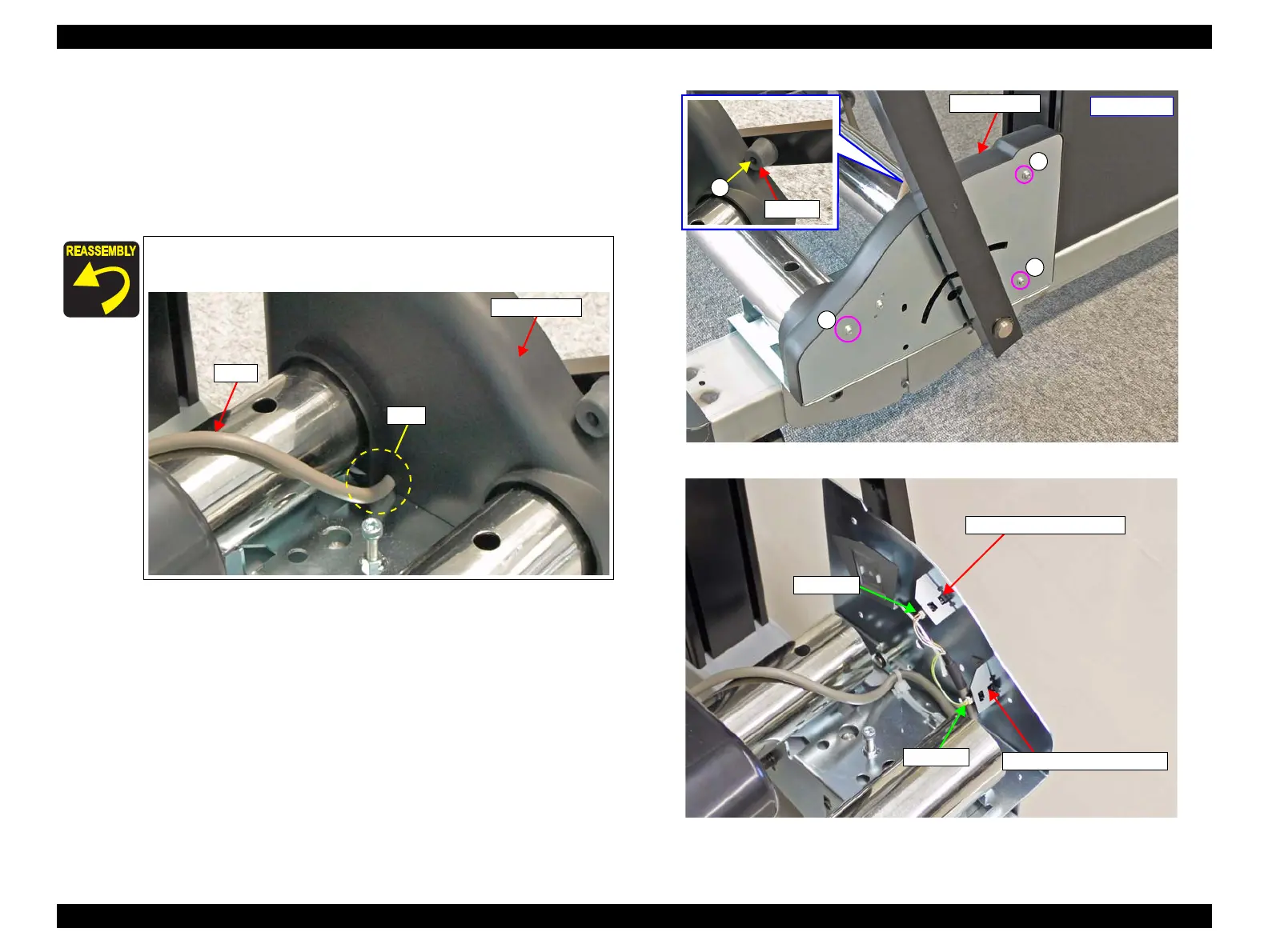
1. Remove the screw, and remove the stopper.
A) Silver M4x12 screw: 1 pcs
2. Remove the three screws, and remove the Sensor Cover.
B) Silver M3x8 P-tite screw with built-in washer: 3 pcs
3. Disconnect the cable from the connector of the sensor.
4. Disengage the hooks, and remove the sensor.
Figure 3-159. Removing the Sensor Cover
Figure 3-160. Removing the Tension Bar Upper Sensor
Route the cable through the hole on the Sensor Cover shown in the
figure below.
Sensor Cover
- Right side -
Tension Bar Lower Sensor
Tension Bar Upper Sensor
Connector
Connector
 Loading...