Maintenance 8. Arm #4
G6 Rev.21 161
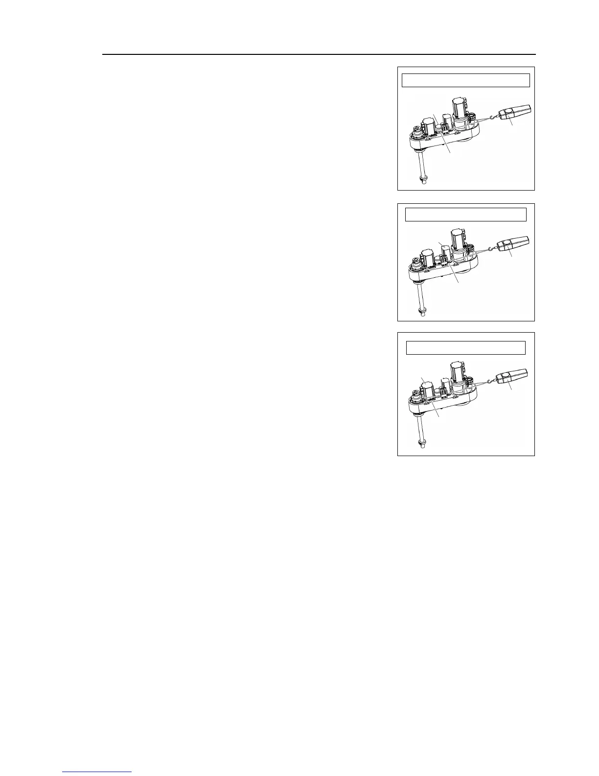
Apply the proper tension to the
4 intermediate shaft unit.
To do so, pass a suitable cord or string
4 intermediate shaft unit near its
Then, pull the cord using a
force gauge or similar tool to apply the
tension shown in the figure on
Joint #4
Intermediate
shaft unit
U2 belt tension = 130 N
(13.2
kgf)
Apply the proper tension to the
To do so, pass a suitable cord or string
4 motor unit near its mounting plate.
Then, pull the cord using
similar tool to apply the
U1 belt tension = 70 N (7.1 kgf)
Apply the proper tension to the
To do so, pass a suitable cord or string
3 motor unit near its mounting plate.
Then, pull the cord using
similar tool to apply the
Make sure that the brake cables do not
Z belt tension = 80 N (8.1 kgf)
.
Connectors X231, X31, X32, X63.
-bundle the cables in their original positions with a wire tie removed in step (5).
Do not allow unnecessary strain on the cables.
top cover and arm bottom cover.
For details, refer to Maintenance: 3. Covers.
calibration of Joints #3 and #4.
For details, refer to Maintenance: 13. Calibration.