EPSON Stylus CX4100/CX4200/CX4700/CX4800/DX4200/DX4800/DX4850 Revision A
DISASSEMBLY/ASSEMBLY Printer Section 154
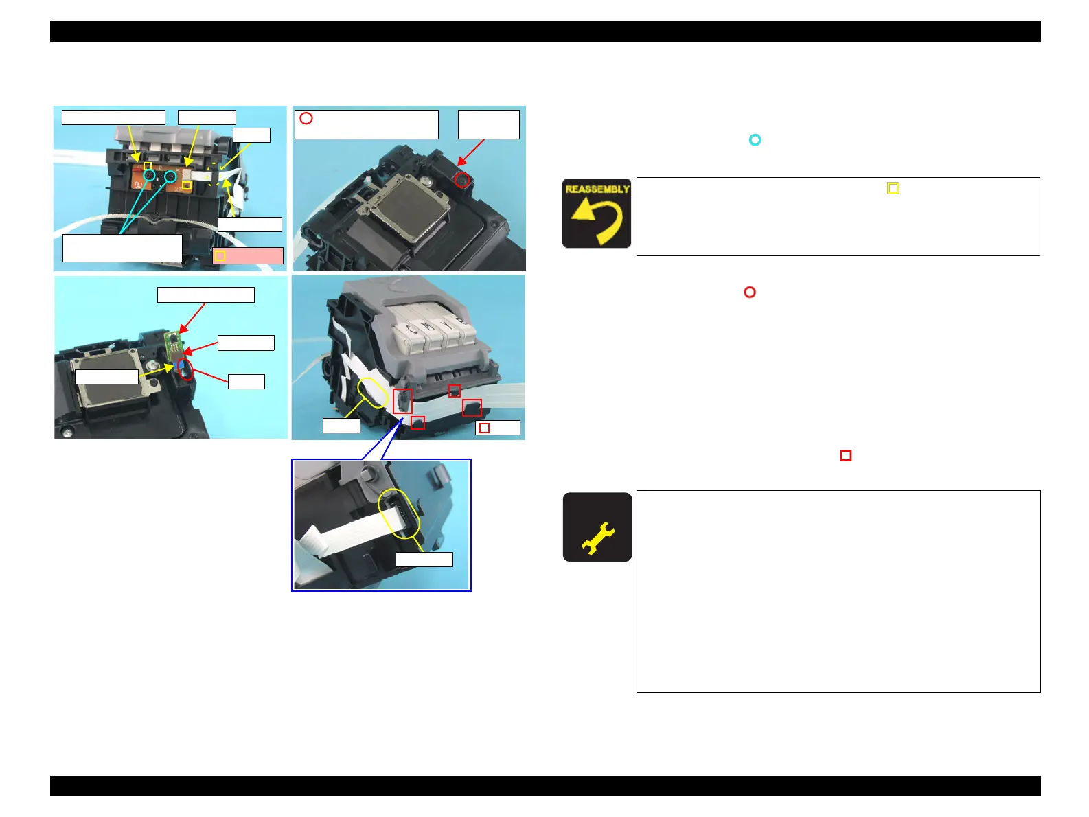
External view (3)
Figure 4-37. Removing Carriage Unit (3)
CR Encoder Removal
1. Disconnect the Head FFC from the connector of the CR Encoder Board, and
pull out the Head FFC from the notch of Carriage.
2. Remove the screws (x2, ) that secure the CR Encoder Board, and remove
the CR Encoder Board
PW Sensor Board Removal
1. Remove the screw (x1, ) that secures the PW Sensor Cap, and remove the
PW Sensor Cap.
2. Disconnect the Head FFC from the connector of the PW Sensor Board, pull
out the Head FFC from the notch of the Carriage, and remove the PW Sensor
Board.
Head FFC Removal
1. Remove the Printhead from the Carriage Unit.
2. Pull out the Head FFC from the notch of the Carriage.
3. Release the Head FFC from the tabs (x4, ) that secure the Head FFC.
4. Disconnect the Head FFC from the connector of the CSIC board.
PW Sensor Board
Connector
Notch
Head FFC
PW Sensor
Cap
C.B.P. (P1) 1.7x5 F/ZB
(2±0.5kgfcm)
Tabs
Notch
CR Encoder Board Connector
C.P.B. (P1) 1.7x5 F/ZB
(2±0.5kgfcm)
Guide Pins
Notch
Head FFC
Connector
Match the guide pins of the Carriage (x2, ) with the positioning
hole (x2) of the CR Encoder Board.
A D J U S T M E N T
R E Q U I R E D
After replacing the Carriage Unit with a new one, always apply
grease KEN to the specified parts.
• Refer to Figure 6-7 (p191) for details.
After replacing the Carriage Unit, perform the adjustment in the
following order. (Refer to Chapter 5 “ADJUSTMENT”)
1. “PG Adjustment”
2. “Top Margin Adjustment”
3. “Head Angular Adjustment”
4. “Bi-D adjustment”
5. “PW Sensor Adjustment”
6. “First Dot Adjustment”
 Loading...


