Maintenance 9. Joint #1
168 VT Rev.1
the AMP board fixing plate (with AMP board) to a new
Hexagon socket head cap bolts: 2-M3×6
Tightening torque: 2.0 ± 0.1 N·m
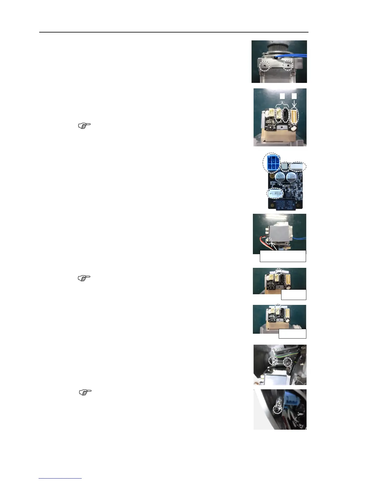
Connect the following connectors of
the motor.
A: Signal cable connectors (for motor × 2)
B: Signal cable connector (for AMP board)
the signal cable connector (for motor) is the
the following connectors of the AMP board.
A: Power cable connector
B: Brake connector
C Signal cable connector (for AMP board)
D: Motor connector
the thermal sheet on the bottom of the motor unit.
For the attaching position, refer to
the picture on the right.
that the entire surface of the thermal sheet
the rear side of the motor unit without lifting
the timing belt through the motor pulley and loosely
to the Arm #1.
Hexagon socket head cap bolts: 3-M4×22
(with slotted hole washer)
grooves of the timing belt are fit
of the pulley completely.
When securing the motor unit loosely, make sure that the
motor unit
can be moved by hand and it does not tilt when
If the unit is secured too loose or too tight,
the belt will not have proper tension.