Maintenance 10. Joint #2
178 VT Rev.1
Release the Joint #2 brake.
Tilt the Arm #2 and push it against the Arm #1.
The Arm #2 falls by its weight when the Joint #2 motor unit is
Therefore,
release the brake and tilt the Arm #2 in
When pushing the arm, push the Arm #
If a strong impact is applied to the joint, the Manipulator may get damage.
Turn OFF the Manipulator.
Cover.
For details, refer to Maintenance: 7.2 Arm #2 Cover.
Cut off the wire tie bound inside the Arm #2.
Wire tie : AB150 × 3
AB100 × 2
Be careful not to cut the harness.
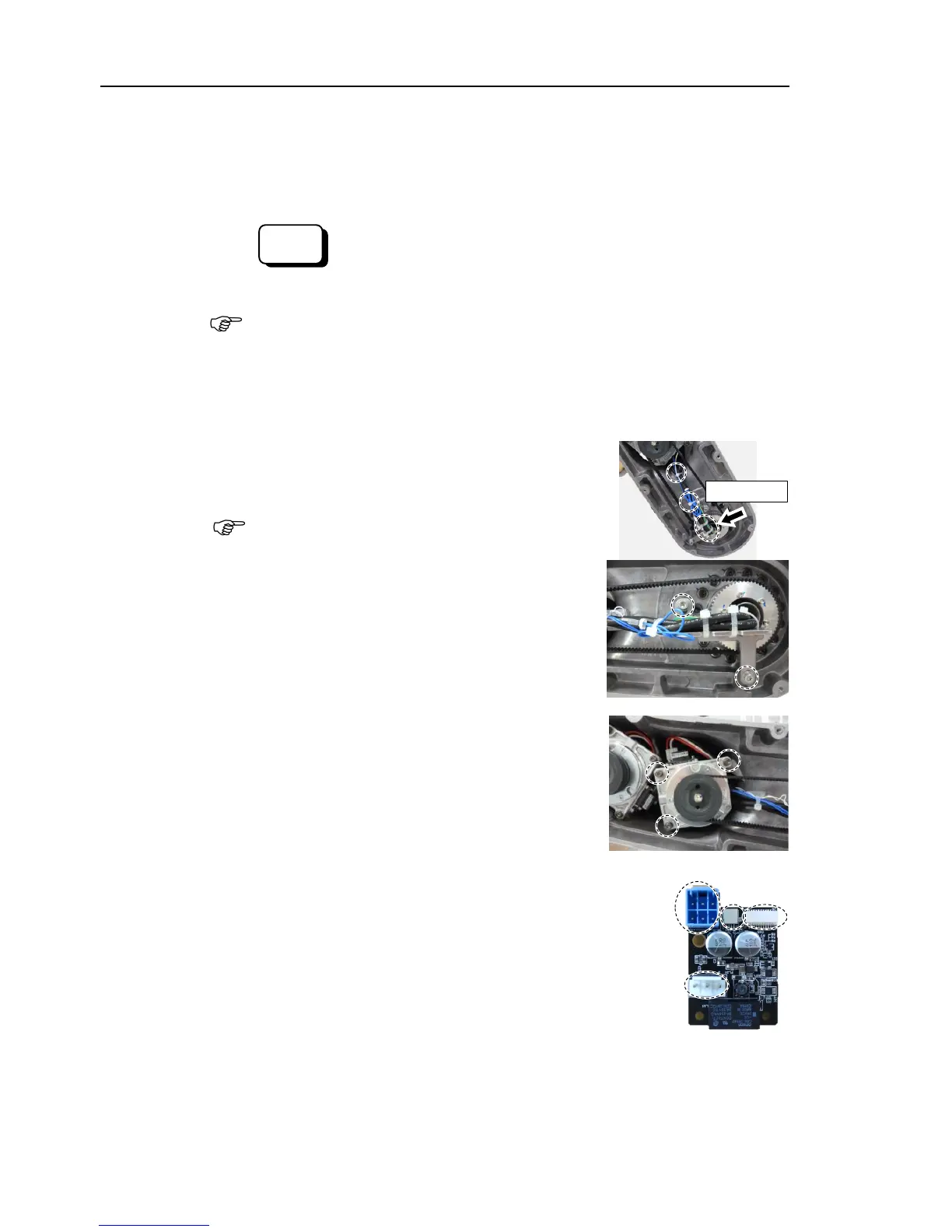
Remove the cable fixing plate on
Joint #2 side)
Hexagon socket head cap bolts with captive
washer: 2-M4×12
Loosen the mounting screws of the Joint #2 motor
unit and remove
the Joint #2 timing belt.
Hexagon socket head cap bolts: 3-M4×22
(with slotted hole washer)
the motor unit from the Arm #2.
Hexagon socket head cap bolts: 3-M4×22
(with slotted hole washer)
Disconnect the following connectors from
the AMP board.
A: Power cable connector
B: Brake connector
C: Signal connector (for AMP board)
D: Motor connector