EasyManuals Logo

Epson VT6L User Manual

Epson VT6L
274 pages
To Next Page IconTo Next Page
To Previous Page IconTo Previous Page
Page #205 background imageLoading...
Page #205 background image
Maintenance 11. Joint #3
VT Rev.1 189
Joint #3
Motor
Installation
(1)
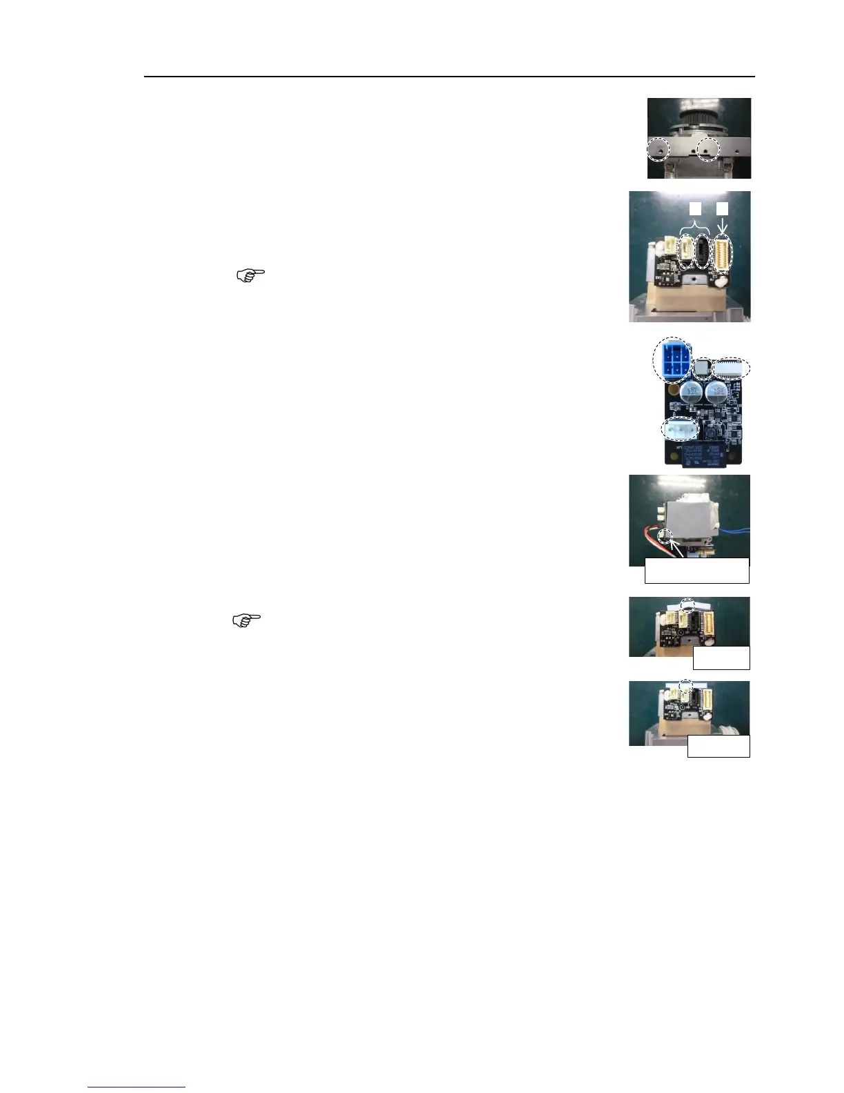
Fix the AMP board fixing plate (with AMP board)
to a new
motor unit.
Hexagon socket head cap bolts: 2-M3×6
Tightening torque: 2.0 ± 0.1 N·m
(2)
Connect
the following connectors of the motor.
A: Signal cable connectors (for motor × 2)
B: Signal cable connector (for AMP board)
Connector for
the signal cable connector (for motor) is the
same
color.
A
B
(3)
Connect
the connectors of the AMP board.
A: Power cable connector
B: Brake connector
C Signal cable connector (for AMP board)
D: Motor connector
A
B
D
C
(4)
Attach
the thermal sheet on the bottom of the motor unit.
For the attaching position, refer to
the picture on the right.
Match the corners
Make sure
that the entire surface of the thermal sheet
contacts with
the rear side of the motor unit without lifting
up
the center of the sheet.
Wrong
Correct
NOTE
NOTE

Table of Contents

Other manuals for Epson VT6L

Questions and Answers:

Question and Answer IconNeed help?

Do you have a question about the Epson VT6L and is the answer not in the manual?

Epson VT6L Specifications

General IconGeneral
BrandEpson
ModelVT6L
CategoryRobotics
LanguageEnglish

Related product manuals