Maintenance 12. Joint #4
198 VT Rev.1
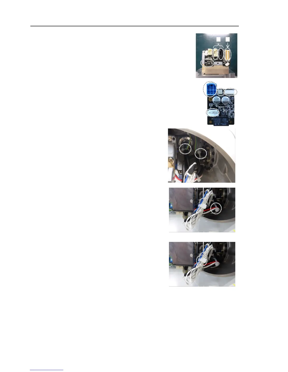
Connect the following connectors of the motor.
A: Signal cable connectors (for motor × 2)
B: Signal cable connector (for AMP board)
the signal cable connector (for motor) is
the connectors of the AMP board.
A: Power cable connector
B: Brake connector
C Signal cable connector (for AMP board)
D: Motor connector
Pass the wire tie through the hole on the
plate
Bind the following cables with the wire tie.
Wire tie: AB150
Power cable
Signal cable (for motor)
Ground wire
the following cables between the Jo
int #3 motor with the
wire tie.
Wire tie: AB100
Power cable
Signal cable (for motor)
Motor cable
the following cables between the Jo
int #3 motor with the
wire tie.
Wire tie: AB100
Signal cable (for AMP board)
Signal cable (for motor)
Brake cable
the Arm #3 cover.
Reference: Maintenance 7.3 Arm #3 Cover