EasyManuals Logo

Epson VT6L User Manual

Epson VT6L
274 pages
To Next Page IconTo Next Page
To Previous Page IconTo Previous Page
Page #248 background imageLoading...
Page #248 background image
Maintenance 18. Controller Unit
232 VT Rev.1
Controller Unit
Removal
(1)
Turn ON
the Manipulator.
(2)
Remove
the connector plate.
Reference: Maintenance 7.7 Connector Plate
(3)
Disconnect
the TP connector which is connected (inside) the connector plate.
(
4)
Unscrew
the
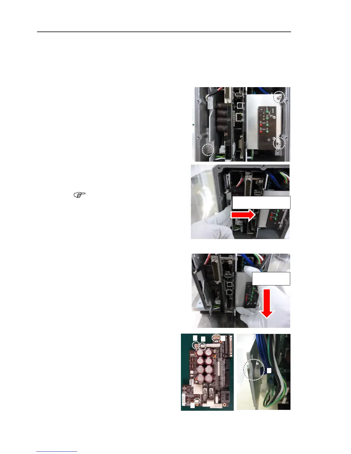
mounting screws of the
controller unit.
Hexagon socket head cap bolts:
3-M4×10 (with a plain washer)
(
5)
Pull out the controller unit from
the
Manipulator base.
When pulling it out,
firstly push the plate of
the controller unit
to the right (see the picture) gently, then
remove the
thermal sheet on the base and
the
controller unit.
Next, pull
the controller unit forward.
Gently push to the right
Pull it forward
(
6)
Disconnect
the following
connectors of the controller
unit.
A: Power cable connector
B: Signal cable connector
C: Hand I/O connector
D: LED connectors × 2
D
A
C
B
D
NOTE

Table of Contents

Other manuals for Epson VT6L

Questions and Answers:

Question and Answer IconNeed help?

Do you have a question about the Epson VT6L and is the answer not in the manual?

Epson VT6L Specifications

General IconGeneral
BrandEpson
ModelVT6L
CategoryRobotics
LanguageEnglish

Related product manuals