Maintenance 18. Controller Unit
VT Rev.1 233
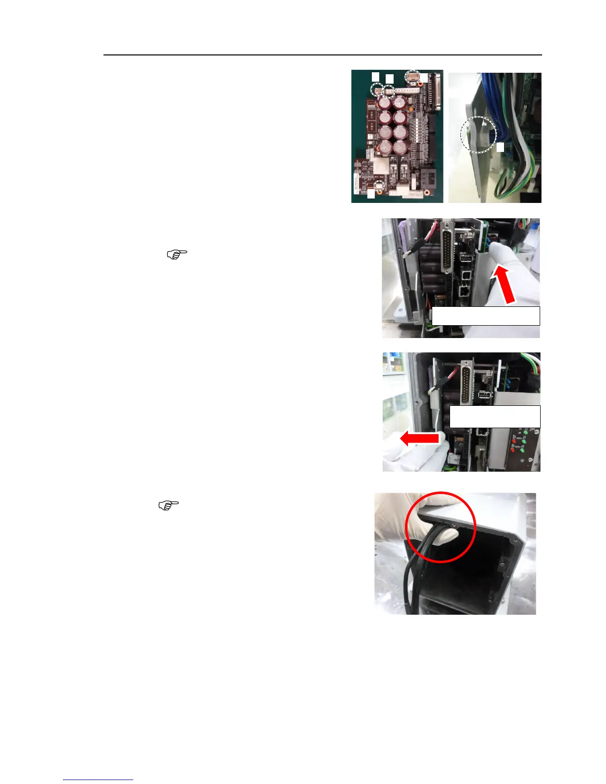
the following connectors to
controller unit.
A: Power cable connector
B: Signal cable connector
C: Hand I/O connector
D: LED connectors × 2
the controller unit into the base.
Insert the controller unit while moving it
t
o the right (see the picture).
Then, gently move the plate of the
controller
left and let the
thermal sheet
contacts with the wall inside
Move it to the right to insert
the controller unit while
the Joint #1 motor at the base
opening. Be careful not to push