DESCRIPTION OF OPERATION
0740 801 028
- 26 -
© ESAB AB 2017
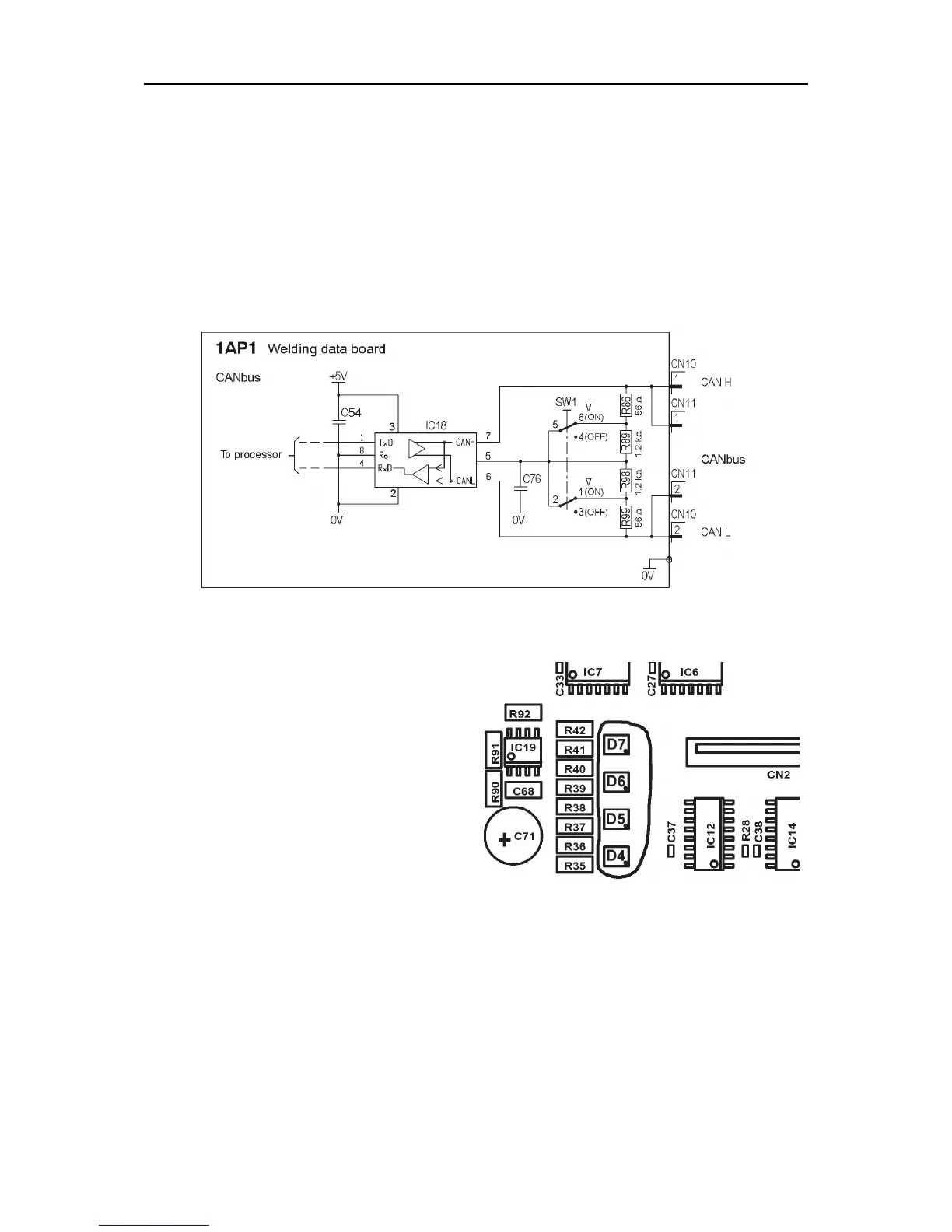
CAN bus & termination
Communication between the welding data board and other units is made via the welding
system's CAN bus. The terminating resistors for the CAN bus are located on the welding
data board 1AP1 and controlled by switch SW1.
• In position “ON”, the CAN bus will be loaded with ~ 120 ohm from resistors R86 and
R99.
• In position “OFF”, the CAN bus will be loaded with ~ 2.5 kohm from resistors R86,
R89, R98 and R99.
Read more about the CAN bus in the service manual for the power source.
Circuit diagram for the CAN bus
Starting sequence
At power-up, the board's micro processor
sets the bus speed for the CAN controller to
500 kbit/s.
The LEDs D4 to D6 on the welding data
board displays the starting sequence from
power-up.
First D4 lights red, then D4, D5 and D6 lights
green.
When the board has been initiated, and is
running the application program, LED D4
flashes continously with a green light.
LED D7 is not used in this application.
LEDs on welding data board 1AP1