-- 25 --
1sxx02cw
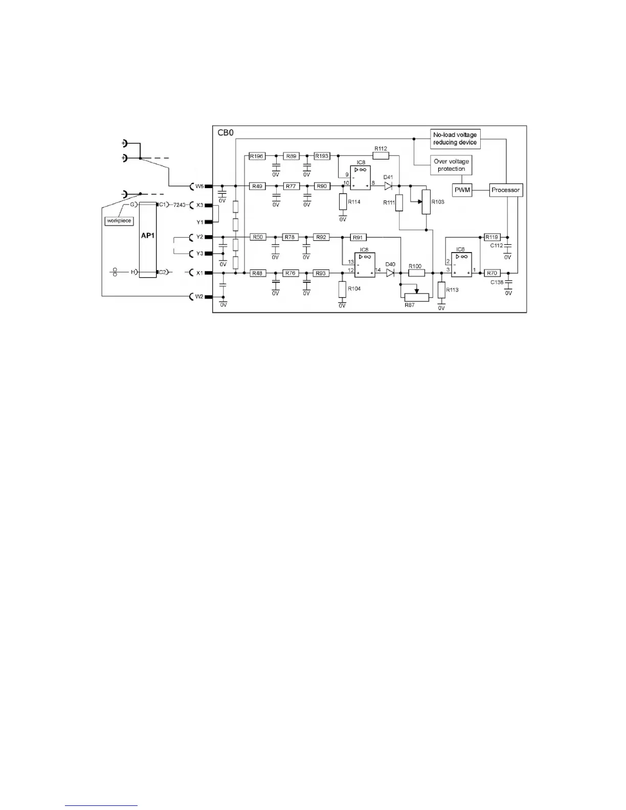
CB0:6 Arc voltage input Mig/Mag
The arc voltage input senses the welding voltage regardless of the welding polarity
or welding method. If sensing via the welding filler wire is turned on, the voltage
present on filler wire will be used; if not, the voltage at the power source terminals
is used instead.
The signal from the arc voltage input drives the welding process controller. On that
basis the controller calculates in real time how much current must flow in the circuit
at the next instant.
The controller activates/deactivates the no--load voltage reduction function.
The arc voltage signal provides data to the power source display panel.
No--load voltage reduction No--load overvoltage protection
This circuits normally shouldn’t operate. Voltage levels were matched to double
forward converter and are much higher as in chopper topology voltages can be
(maximum is rectifier voltage <70V)
Methods of measuring the arc voltage
Various methods of measurement are available by transferring a link among
contacts Y1, Y2 and Y3. When delivered, the link is fitted between Y2 and Y3.
The link must be connected between Y2 and Y3 for MMA and TIG welding.
Welding with the filler wire positive: voltage sensing from the wire.
This is the most common arrangement for MIG welding. Y2 -- Y3 must be linked.
This method of measurement allows for the voltage drop in the supply conductor
(to the welding gun). The input signal is measured between inputs X1 and W2.
Amplifier IC8:14 is active.
Welding with the filler wire negative: voltage sensing from the wire Y2 -- Y3 must be
linked. This method of measurement allows for the voltage drop in the supply
conductor. The input signal is measured between inputs X1 and W5. Amplifier
IC8:8 is active.