-- 26 --
1sxx02cw
Welding with the filler wire positive or negative, without external sensing from the
wire or workpiece. Y2 -- Y3 must be linked. The input signal is measured between
inputs W5 and W2 (the voltage at the power source terminals), as there is no
connection to X1. Amplifier IC8:14 is active.
Welding with the filler wire positive: voltage sensing from the wire and workpiece.
Y1 and Y2 must be linked. This method allows for the voltage drop on both the
supply and return conductors. The input signal is measured between X1 and X3.
Amplifier IC8:14 is active.
Note: If the voltage signal connection to X3 is lost, the power source loses
control of the arc voltage.
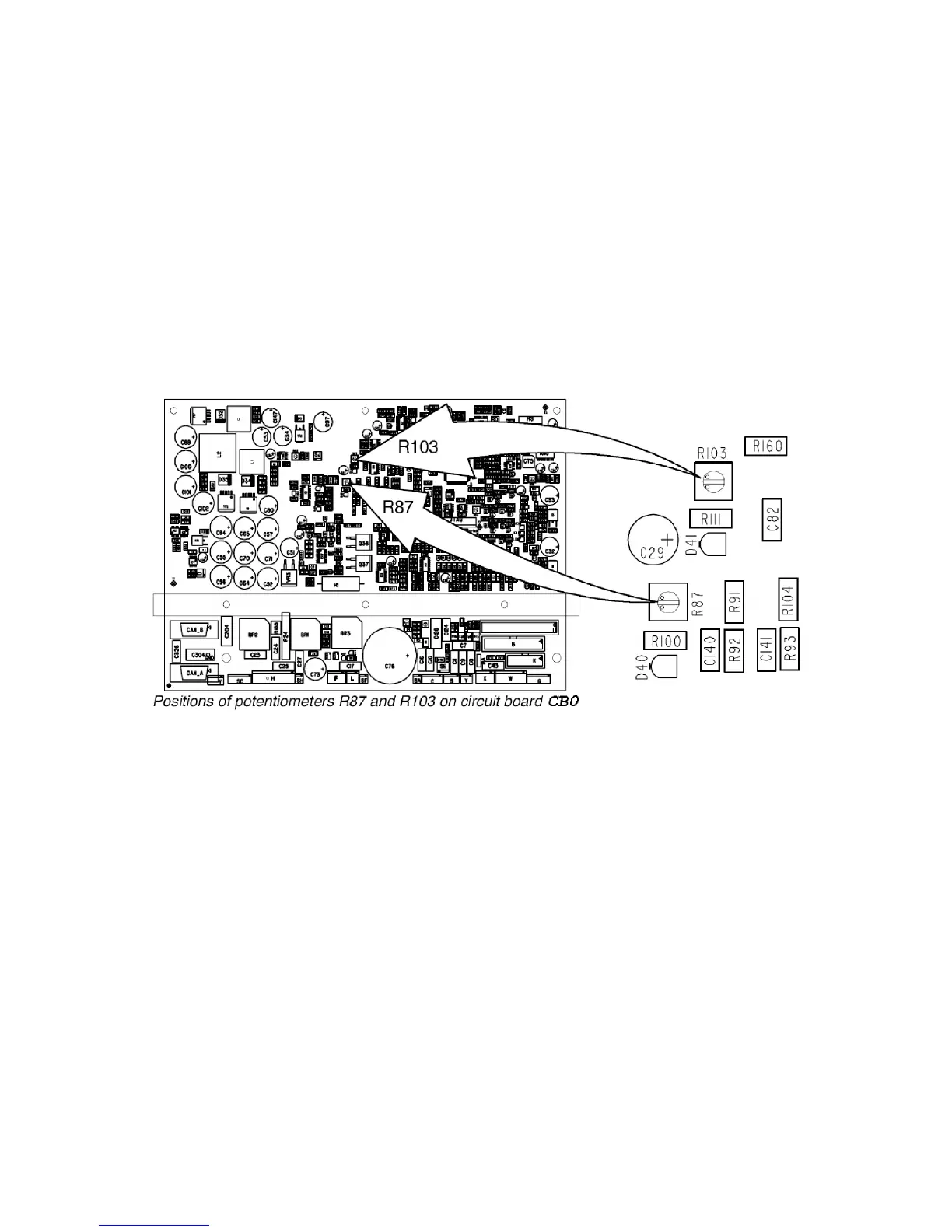
CB0:6.1 Calibration of the arc voltage feedback
The arc voltage input can be calibrated using trimming potentiometers R87 and
R103 on circuit board CB0. The board has been calibrated in the factory: further
adjustment should not normally be necessary.
Check that there is a short--circuiting link across connectors Y2 -- Y3: see the circuit
diagram above. Connect a wire feed unit to the power source. Connect long
welding current cables, to give an appreciable voltage drop in the cables. Connect
a wire to the feed rollers, and connect an external voltmeter, as shown in the
diagrams on next page. Set the power source to MIG short arc welding mode, and
apply a resistive load to give a current of 100 A at 25 -- 30 V. Start the power
source from the welding gun trigger contact and adjust the current by changing the
wire feed speed setting. Adjust the voltage by varying the load resistor.
Use properly calibrated external voltmeter to measure the output voltage of the
machine.
 Loading...