Operation & Software Manual
108
Direct Drives & Systems
Chapter C: System functions ETEL Doc. - Operation & Software Manual # DSC2P 903 / Ver. F / 3/6/05
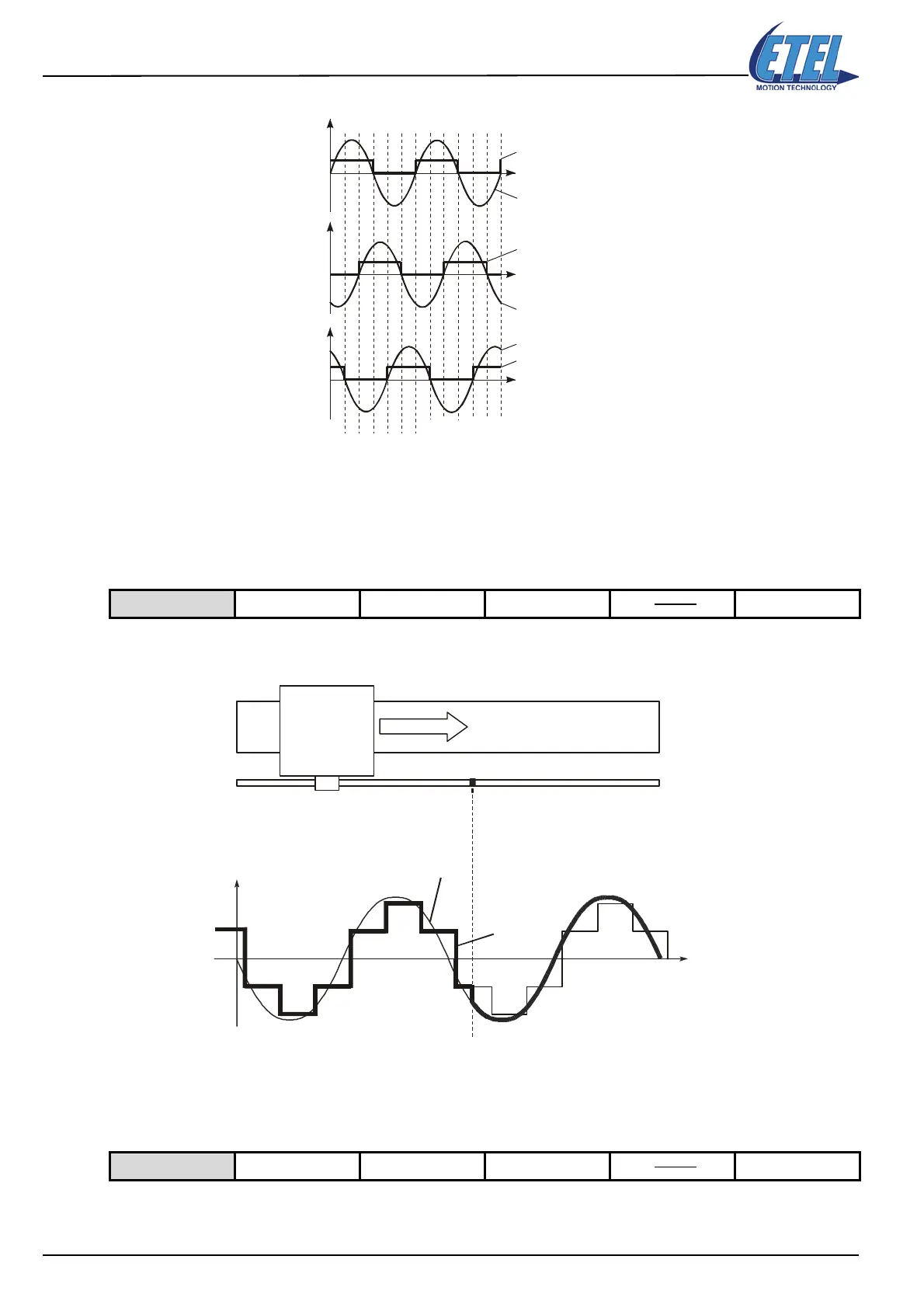
One period of the signals is divided into 6 different parts. These parts (as mentioned above) are associated to
the following values of monitoring M48: 5, 0, 1, 2, 3 and 4 respectively.
Remark: M48 = 255 indicates that there is a cabling problem of the digital Hall effect sensor.
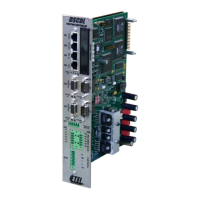
• K90 = 3: Phasing with digital Hall effect sensor (mode 1)
The commutation is done with a digital Hall effect sensor as far as the reference mark is found then the position
encoder is used with the value stored in parameter K53 (phase shift adjustment).
Caution: When parameter K90 or K68 is modified, the command AUT = 10 must be executed to re-calculate
parameter K53.
• K90 = 4: Phasing with digital Hall effect sensor (mode 2)
The commutation is done with a digital Hall effect sensor up to the first edge and with the position encoder up
to the reference mark is found. From then on, the commutation is done with the position encoder with the value
Available on DSC2P DSC2V DSCDP DSCDL DSCDM
Available on DSC2P DSC2V DSCDP DSCDL DSCDM
Position
Position
Position
H1
H2
H3
V1-2
V2-3
V3-1
501234
.......
Value of M48
MOTOR
ENCODER
Reference mark
Encoder with K53 (LKT)
Hall