Operation & Software Manual
174
Direct Drives & Systems
Chapter C: System functions ETEL Doc. - Operation & Software Manual # DSC2P 903 / Ver. F / 3/6/05
13.5 Position capture on digital inputs
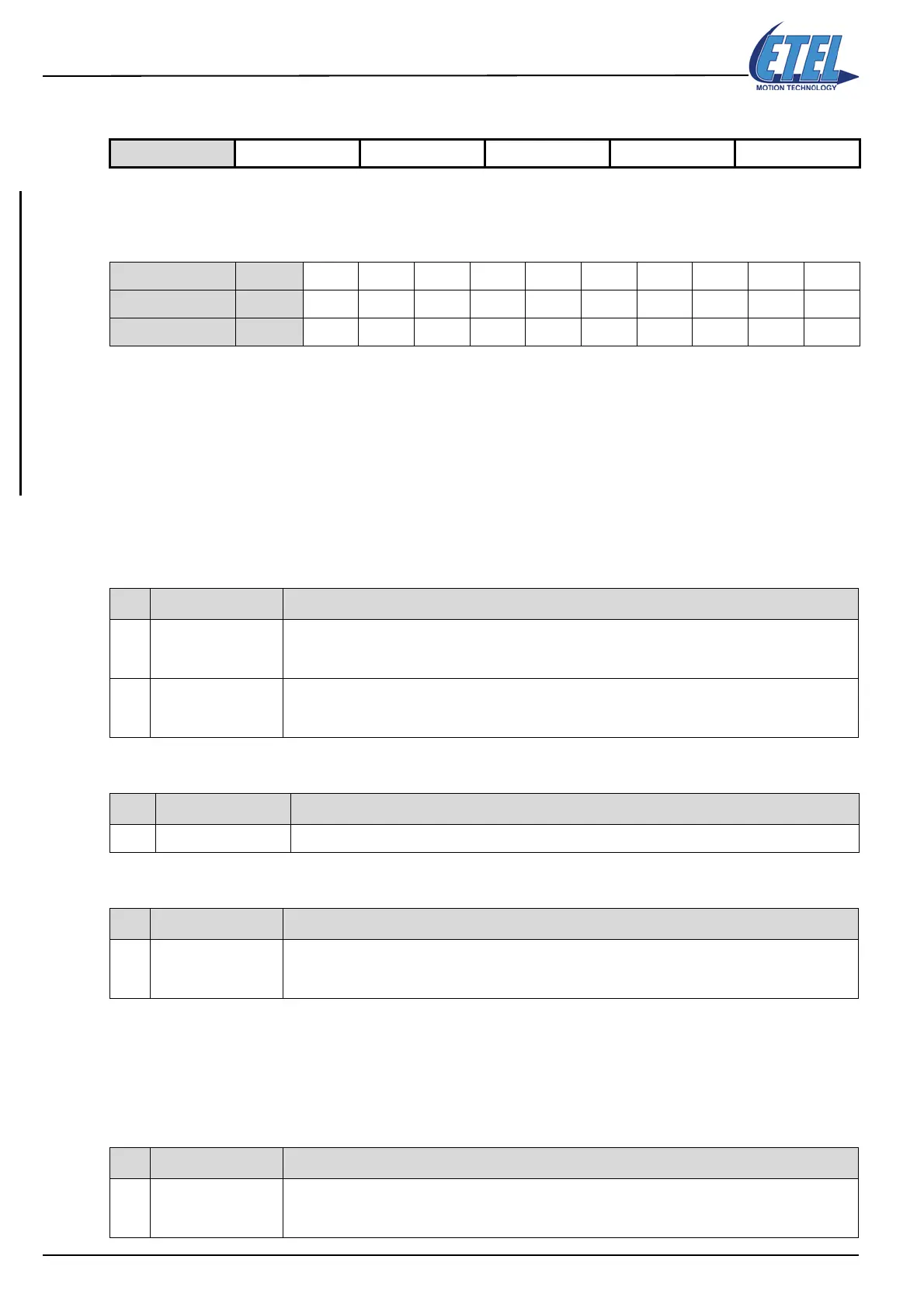
The number of digital inputs is different from a position controller to another. Here is a table giving the number
of digital inputs present on each position controller (refer to the corresponding ’Hardware Manual’ for more
information):
Caution: On the DSC2P and DSC2V, the digital inputs 5, 6 and 7 are NOT tested for the position
capture.
On the DSCDM, the digital inputs and outputs are on the same pin. The pin must be selected in
order to have an input or an output. It is NOT possible to have both on the same pin. To
use a pin as a digital input, the bit corresponding to this input MUST be equal to 0 in parameter
K171 (otherwise the hardware of the controller and the one of the user can be damaged).
The inputs are tested every FTI (FTI = 41.67µs for the DSC2P/DSC2V and 55.56µs for the DSCDP, DSCDL
and DSCDM) and when the condition(s) defined by parameters K178 and/or K179 is true the position is
captured and saved in monitoring M12 [upi].
Remark: At least one condition defined by parameter K178 or K179 must be met to have a position capture.
Parameter K159 allows the user to invert the digital inputs for position capture
Remark: If parameter K159 inverts the digital inputs, the rising edges become falling edges and vice versa.
DIN1 cannot be inverted by parameter K159 if K33 = 0 because DIN1 is a safety input.
Parameter K159 does not modify monitoring M50. It is only for the position capture test that the
digital inputs are inverted.
Parameter K182 allows the user to activate the position capture on the digital inputs.
Available on DSC2P DSC2V DSCDP DSCDL DSCDM
DSC2P / DSC2V DIN # 109 - 7654321
DSCDP / DSCDL DIN # 109------21
DSCDM DIN # -------321
K Name Comment
K178
Mask of the DINs
on rising edge
Defines the mask of the digital inputs on the rising edge:
K178, depth 0, bit 0, 1, 2, 3, 8 and 9 (bit0=DIN1, bit1=DIN2, bit2=DIN3, bit3=DIN4, bit8=DIN9 and
bit9=DIN10)
K179
Mask of the DINs
on falling edge
Defines the mask of the digital inputs on the falling edge:
K179, depth 0, bit 0, 1, 2, 3, 8 and 9 (bit0=DIN1, bit1=DIN2, bit2=DIN3, bit3=DIN4, bit8=DIN9 and
bit9=DIN10)
M Name Comment
M12 Real position on DIN Gives the real position (upi) captured on digital inputs
K Name Comment
K159 Inversion of the DINs
Inverts the digital inputs for position capture:
K159, depth 0, bit 0, 1, 2, 3, 8 and 9 (bit0=DIN1, bit1=DIN2, bit2=DIN3, bit3=DIN4, bit8=DIN9 and
bit9=DIN10)
K Name Comment
K182
Position capture
on DIN
Activates the position capture on digital input according to parameters K178 and K179. Writing a 1 in
parameter K182 activates the capture and resets (=0) bit# 2 of SD2 (monitoring M61) and bit# 30 of
monitoring M63. Writing a 0 stops the process.