Operation & Software Manual
200
Direct Drives & Systems
Chapter C: System functions ETEL Doc. - Operation & Software Manual # DSC2P 903 / Ver. F / 3/6/05
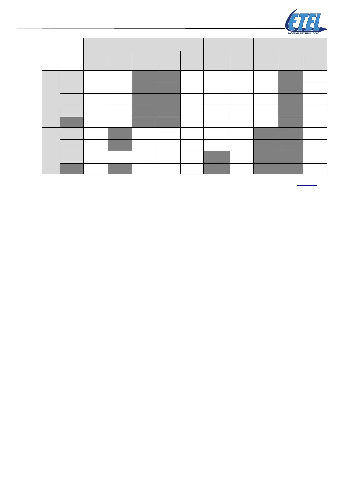
Remark: Masks are programmed with parameters K183, K184 and K185 (alias TMK) (refer to §13.9.5).
The values selected by the Mask are in bold in the table above; they will be activated by the
triggers. The other values are not controlled, they remain normally in their previous state.
Now, we are ready to program the triggers described above:
:79.1 ;Autostart label
DOUT.1=0 ;All digital outputs of the controller are set to 0
TCL.1 ;All triggers tables are erased
TNB.1=4 ;The table is defined with 4 triggers per mapping (alias of parameter K187)
;Mapping #0 (definition triggers E
0,
E
1,
E
2,
E
3
)
E0:0.1=0x00010081 ;Positive trigger (0x81) and action 1 (0x01), controller's DOUTs & SD2
E0:1.1=1 ;Controller outputs =0001 bin. DOUT1=1 (masked by TMK), other DOUTs = 0
E0:2.1=1 ;’Status Drive’ SD2 bits = 01 bin. Bit# 9=0, Bit# 8=1 (masked by parameter K184)
E0:3.1=10000 ;Trigger position = 10000 [upi]
E1:0.1=0x00010082 ;Negative trigger (0x82) and action 1 (0x01), controller's DOUTs & SD2
E1:1.1=0 ;Controller's outputs = 0000 bin. All the DOUTs = 0 (masked by TMK)
E1:2.1=0 ;’Status Drive’ SD2 bits = 00 bin. Bit# 9=0, Bit# 8=0 (masked by parameter K184)
E1:3.1=20000 ;Trigger position = 20000 [upi]
E2:0.1=0x00010081 ;Positive trigger (0x81) and action 1 (0x01), controller's DOUTs & SD2
E2:1.1=2 ;Controller's outputs = 0010 bin. DOUT2=1(masked by TMK), other DOUTs = 0
E2:2.1=1 ;’Status Drive’ SD2 bits = 01 bin. Bit# 9=0, Bit# 8=1 (masked by parameter K184)
E2:3.1=30000 ;Trigger position = 30000 [upi]
E3:0.1=0x00010082 ;Negative trigger (0x82) and action 1 (0x01), controller's DOUTs & SD2
E3:1.1=3 ;Controller's outputs = 0011 bin. DOUT2 & 1=1 (masked by TMK), other DOUTs
= 0
E3:2.1=1 ;’Status drive’ SD2 bits = 01 bin. Bit# 9=0, Bit# 8=1 (masked by parameter K184)
E3:3.1=40000 ;Trigger position = 40000 [upi]
DSC2P outputs DSO-HIO outputs ’Status Drive’ bits
DOUT4
Bit 3 = 8
DOUT3
Bit 2 = 4
DOUT2
Bit 1 = 2
DOUT1
Bit 0 = 1
Dec. val.
E
x
:1.1
XDOUT1
Bit 0 = 1
Dec. val.
E
x
:1.1
SD2
Bit 9 = 2
SD2
Bit 8 = 1
Dec. val.
E
x
:2.1
Mapping #0
E
0
00
0 1 1 00
0
1 1
E
1
00
0 0 0 00
0
0 0
E
2
00
1 0 2 00
0
1 1
E
3
00
1 1 3 00
0
1 1
Mask 0 0
1 1 3 00
0
1 1
Mapping #1
E
4
0
0
00
0 000 0 0
E
5
0
1
00
4 001 0 2
E
6
0000
0 1 1
1 1 3
Mask
0 1
00
4 1 1 1 1 3