fig_821_2
ES
S
B H M
I
D int
fig_821_3
2
1
3
29
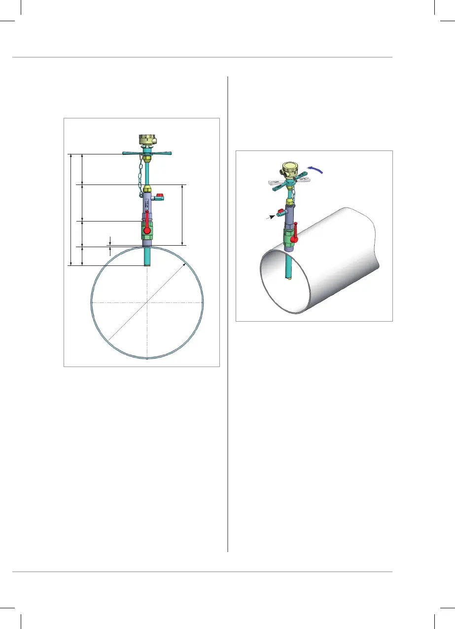
8.2.1 MEAN AXIAL VELOCITY POINT
(1/8 inside diameter)
Legend:
D: Actual inner diameter
S: thickness of the pipe
B: Fixed distance
H: Body constant size (140mm)
I: insertion depth (Dint / 8)
M: Check for the measurement of insertion
ES: Euromag original parts standard size (225mm)
L: total size of the device (400mm)
M = Ltot.-ES-S-(Dint/8)
M = 175-S-Dint./8
Example: D = 200mm, S = 3mm
8.2.2 ALIGNMENTS
Align the indication arrow on the handles of the
sensor with the flow direction
Legend:
1. Loosen the screw
2. Align parallel to the pipe (within 2°)
3. Tighten to 40Nm (30 ft lbf)
M = 175-25-3 = 147
8.2.3 Programming
Program the electronics with the right value of
diameter (see section 10.3.2 Diameter setup).
L tot: 400 mm
See notes:
8. INSERTION METERS
 Loading...