fig_2_1 fig_2_2
10
EUROMAG | MC608 | TD210-1
www.euromag.com
1. PRELIMINARY NOTES
The main parts composing the electromagnetic flow meter consists of:
A. The sensor – is installed in the pipes using flanges or threaded attachments or clamp attachments
B. The converter – may be installed on the sensor (in compact version), or nearby (in remote version)
connected via two cables.
Electromagnetic flow meters have many important advantages with respect to relevant mechanical
counterparts, including among the others: outstanding long term stability, maximum process reliability, no
need for maintenance. Consequently, these sensors can deliver accurate and reliable measurements for
many years.
Please see the paragraphs below for more detailed instructions on correct installation.
ELECTROMAGNETIC FLOW METERS ARE SPECIFICALLY DESIGNED
TO WORK UNDER FEW BASIC CONDITIONS:
1. LIQUID MUST BE CONDUCTIVE
2. THE PIPE MUST ALWAYS BE COMPLETELY FILLED
3. INLET AND OUTLET DISTANCES MUST BE THOSE RECOMMENDED
NOTE
2. GENERAL PRECAUTIONS
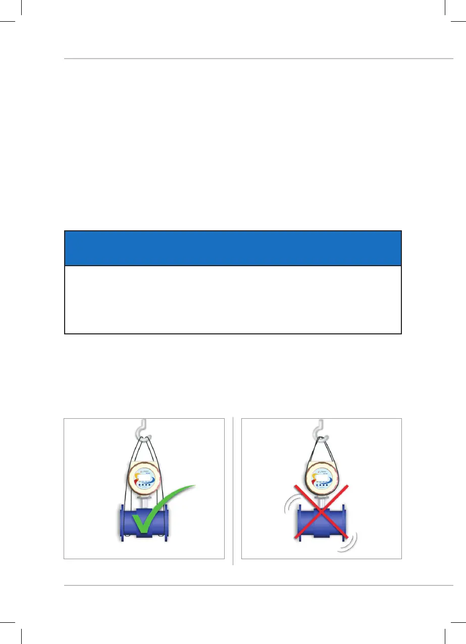
The proper lifting method is shown in Figure fig_2_1, while it must be avoided that shown in Figure fig_2_2; to
be noticed, do NOT raise the flow meter gripping the converter, but always holding it on the sides.
 Loading...