fig_333_3
fig_334_1
fig_333_2
fig_333_1
15
3.3.4 CHARTS OF MAXIMUM
ALLOWABLE TIGHTENING TORQUES
Standard bolts must be well lubricated and tightened
evenly around the gasket. If the bolts are tightened
excessively, they may result in leaks or damage to
the flow meter or to the pipe. Carefully follow any
instructions provided by the graphics, carefully check
the correct centring of the sensor before attaching the
flanges and then proceed by following the steps below:
Step 1. approx 50% of maximum tightening torque;
Step 2. approx 80% of maximum tightening torque;
Step 3 100% of the maximum tightening torque
provided in the chart.
All values are theoretical and were calculated
for optimum conditions and use with carbon steel
flanges.
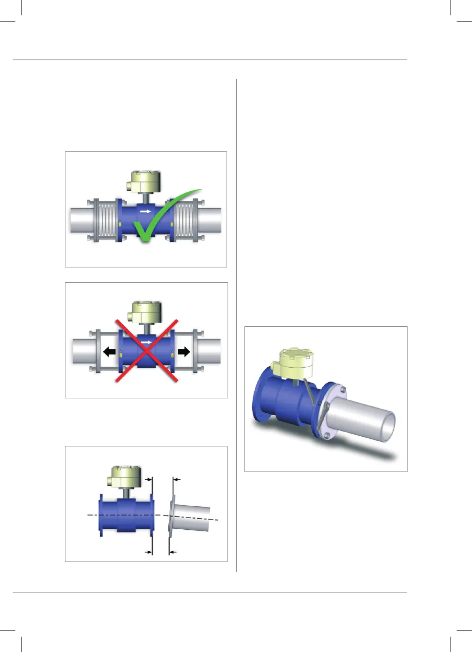
3.3.3 IMPORTANT INSTRUCTIONS ON
MOUNTING
Use elastic pipe fittings where there is not adequate
distance between the sensor and the pipe. Do not
attempt to bring the pipe to the sensor by tightening
the bolts.
Max. allowable deviation of pipe flange faces is
0.5mm
L max
L max. - L min. ≤ 5 mm
3. INSTALLATION OF THE SENSOR
 Loading...