Model 5601ACO2 Automatic Changeover Unit
INSTALLATION Revision 1.2 Page 2-1
2. INSTALLATION
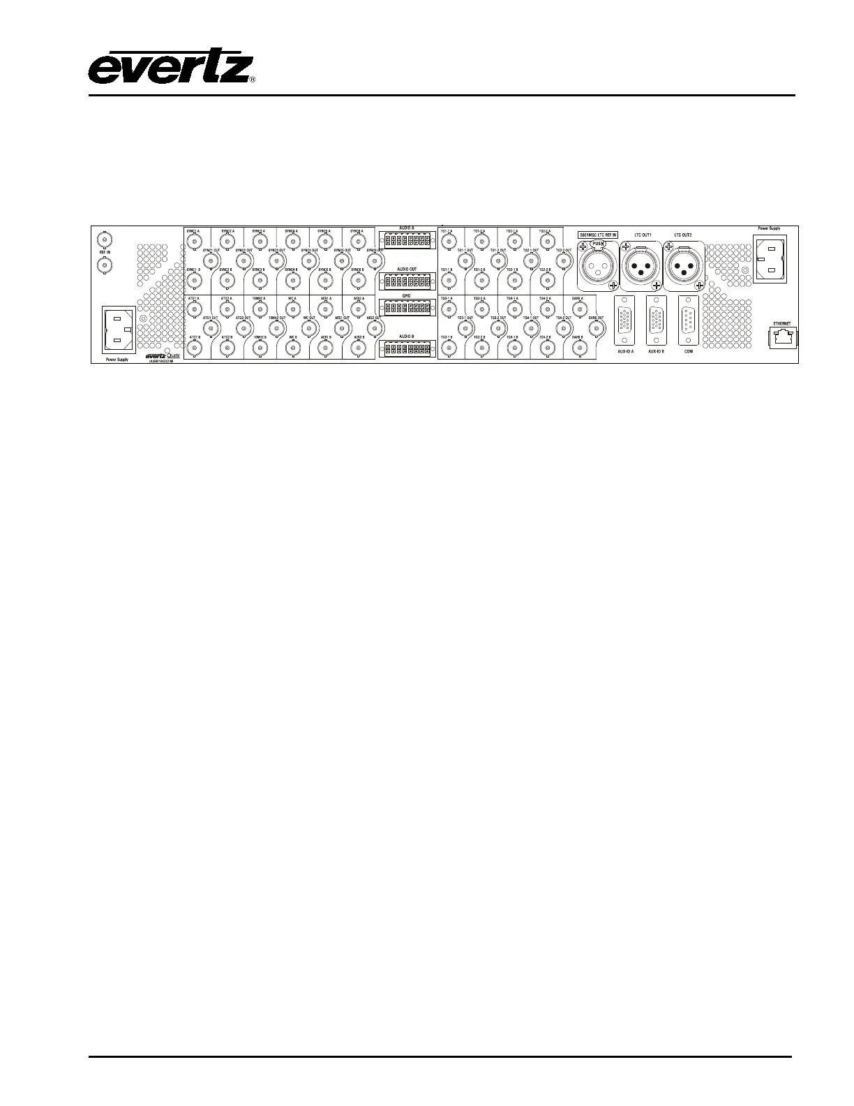
2.1. REAR PANEL
Figure 2-1: 5601ACO2 Rear Panel
The following sections describe the purpose of the rear panel connectors of the 5601ACO2. Sections
2.1.1 to 2.1.4 describe the specific signals that should be connected to the 5601ACO2. Sections 2.4
and
2.5 give more detail on connecting the system.
2.1.1. Coaxial Connections
There are 18 groups of 3 BNC connectors on the 5601ACO2 rear panel. In each group there is one
labelled A, and another labelled B for connection of the indicated signal from the respective 5601MSC
Master Clock/SPG. The BNC labelled OUT provides the output from the auto-changeover unit for
further distribution throughout your company.
DARS OUT: This group of BNC connectors is for connecting the Digital Audio Reference
Signal (DARS) outputs.
AES OUT: This group of BNC connectors is for connecting the Unbalanced AES Audio
outputs.
SYNC 1 to 6: These groups of BNC connectors are for connecting the sync pulse / colour
black outputs.
SD/HD/3G SDI: These groups of BNC connectors are for connecting the HD Test signal
generator outputs.
ANALOG TG: This group of BNC connectors is for connecting the Analog Video Test signal
generator outputs.
10 MHz: This group of BNC connectors is for connecting the 10 MHz outputs.
WORD CLOCK: This group of BNC connectors is for connecting the Word Clock outputs.