Model 5601ACO2 Automatic Changeover Unit
Page 2-4 Revision 1.2 INSTALLATION
Note the following cabling information for this wiring guide:
• Only two pairs of wires are used in the 8-pin RJ 45 connector to carry Ethernet signals.
• Even though pins 4, 5, 7 and 8 are not used, it is mandatory that they be present in the cable.
• 10BaseT and 100BaseT use the same pins; a crossover cable made for one will also work with the
other.
• Pairs may be solid colours and not have a stripe.
• Category 5 cable must use Category 5 rated connectors.
The maximum cable run between the 5601ACO2 and the supporting hub is 300 ft (90 m). The
maximum combined cable run between any two end points (i.e. 5601ACO2 and PC/laptop via network
hub) is 675 feet (205 m). When you have connected the 5601ACO2 and set up the IP address you
should ‘ping’ the device from your PC to make sure that it is connected correctly.
2.1.5. Power Connections
LINE: The 5601ACO2 has redundant universal power supplies operating on 100 to 240VAC,
60 or 50 Hz.
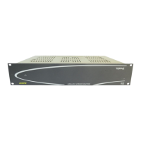
2.2. MOUNTING
The 5601ACO2 is equipped with rack mounting angles and fits into a standard 19 inch by 1 3/4 inch
(483 mm x 45 mm) rack space. The mounting angles may be removed if rack mounting is not desired.
Care must be taken to ensure that the side exhaust vents have a 2” (5cm) clearance to allow for proper
cooling of the unit. The unit may overheat if cables or brackets are blocking the fan exhaust.
2.3. POWER REQUIREMENTS
Power requirements are 100 to 240 volts AC at 50 or 60 Hz. The 5601ACO has redundant universal
power supplies that automatically sense the input voltage. Power should be applied by connecting a 3-
wire grounding type power supply cord to each of the power entry modules on the rear panel. The
power cord should be minimum 18 AWG wire size; type SVT marked VW-1, maximum 2.5 m in length.
CAUTION -
To reduce the risk of electric shock, grounding of the centre pin
of the mains plug must be maintained.