Model 5601ACO2 Automatic Changeover Unit
OPERATION Revision 1.2 Page 3-1
3. HOW TO OPERATE THE AUTOMATIC CHANGEOVER
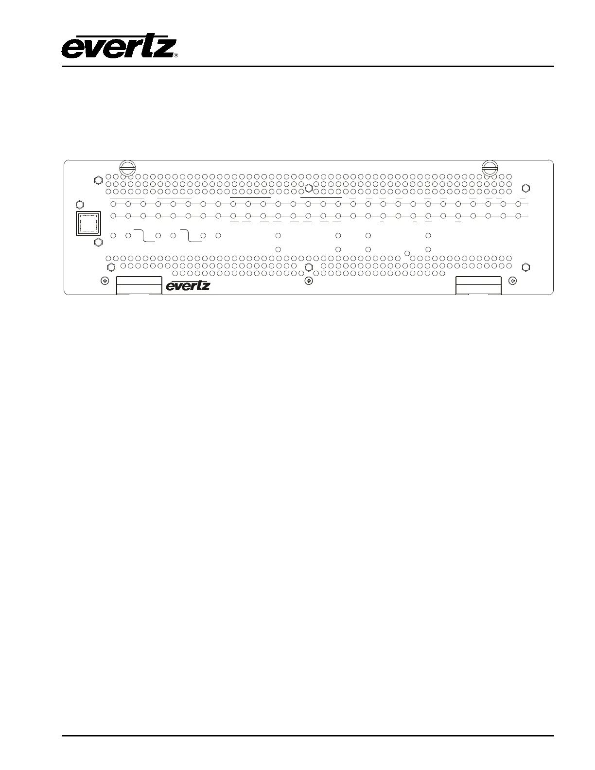
The front panel controls consist of three recessed rocker switches to select the operating mode of the
changeover and 70 LED status indicators.
SYNC
3G/HD/SDI TG
A
B
ATG AES
AUTO MAN
CHANGEOV ER
UNBALANCED
DARS
DARS
AES
BALANCED
AUTOMATIC
CHANGEOVER
model 5601ACO2
MANUAL
CONTROL
MODE
GPI
FRONT
PANEL A B
SELECT
ACTIVE
A
B
GPI
1
2
GPO
1
2
PSU
1
2
LTC MSC GPI
1
2
3 4
5
6 10M WC
1
2
3 4
1 2 1 2
1 2 1 2 1 2
1
2
1 2 1 2 1 2
RECENT
EVENT
TRIGGER
Figure
3-1: Model 5601ACO2 Front Panel
3.1. AN OVERVIEW OF THE STATUS INDICATORS
There are 70 status indicators located on the front panel that show operational status of the 5601ACO2
at a glance.
3.1.1. Operating Mode Indicators
AUTO: This green LED will be On when the unit is operating in the Automatic control mode.
MANUAL: This green LED will be On when the unit is operating in one of the two manual control
modes.
GPI: This green LED will be On when the unit is operating in the Manual GPI control mode.
The LED will be Off when the unit is in the Manual Front Panel or Automatic control
mode.
FRONT PANEL: This green LED will be On when the unit is operating in the Manual Front Panel
control mode. The LED will be Off when the unit is in the Manual GPI or Automatic
control mode.
A: This green LED will be On when the unit is operating in the Manual Front Panel control
mode and that Master A is selected. The LED will be Off when Master B is selected or
the unit is not in the Manual Front Panel control mode.
B: This green LED will be On when the unit is operating in the Manual Front Panel control
mode and that Master B is selected. The LED will be Off when Master A is selected or
the unit is not in the Manual Front Panel control mode.
ACTIVE OUTPUT: These two green LEDs indicate whether Master A or Master B is currently
selected.