5700ACO
Automatic Changeover
Page 8 Revision 1.0
2.1.2. Balanced AES, DARS and Analog Audio Connections*
DARS/AES/ANALOG: These 16 pin terminal strips are for connecting the balanced version of
the AES and DARS signals as well as two balanced analog audio signals.
The output cables can be secured into the removable portion of the
terminal strips using a small screwdriver. The removable part of the
terminal strip is then inserted into the rear panel and secured using the
hold down screws. The pinout of these connectors is shown in Table
2-1.
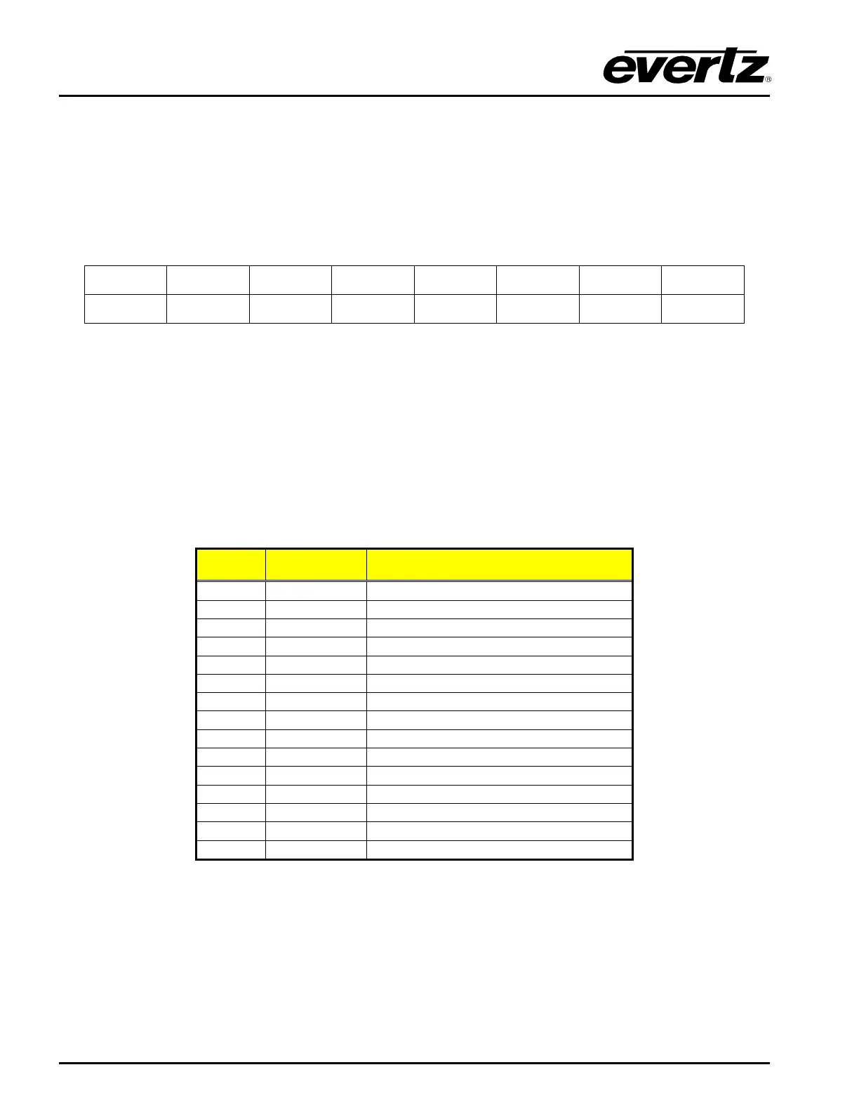
DARS + AES2 + AES1 + GND GND GND RIGHT - RIGHT +
DARS - AES2- AES1 - GND GND GND LEFT - LEFT +
Table 2-1 : DARS/AES/ANALOG Terminal Strip Pin Definitions
* Requires factory installed +AUX hardware option on 5700MSC-IP, IP Master Clocks are available at
extra cost.
2.1.3. Linear Time Code and GPIO Connections*
AUX I/O: These two 15 pin male ‘D’ connectors contain GPI inputs and outputs and two
LTC outputs from the 5700MSC-IP units and should be connected to the AUX I/O
Connectors on the respective 5700MSC-IP units using the straight through 15 pin
cables provided. The pinout of the AUX I/O connector is as follows:
Pin # Name Description
LTC + input to 5700MSC-IP
LTC 1 + output from 5700MSC-IP
LTC 2 + output from 5700MSC-IP
GPO 1 output from 5700MSC-IP
GPO 2 output from 5700MSC-IP
LTC - input to 5700MSC-IP
LTC 1 – output from 5700MSC-IP
LTC 2 - output from 5700MSC-IP
GPI 1 input to 5700MSC-IP
GPI 2 input to 5700MSC-IP
Note that on the B connector, 8 is TX from B, and 9 is TX to A.
Table
2-2 : AUX I/O Pin Definitions
* Requires factory installed +AUX hardware option on 5700MSC-IP, IP Master Clocks are available at
extra cost.