5700ACO
Automatic Changeover
Page 14 Revision 1.0
The GPI and GPO cables can be secured into the removable portion of the terminal strips using a small
screwdriver. The removable part of the terminal strip is then inserted into the rear panel. See Table
2-3
for the pinout of the terminal block.
* Requires factory installed +AUX hardware option on 5700MSC-IP, IP Master Clocks are available at
extra cost.
2.5. CONNECTING THE GENERAL PURPOSE INPUTS AND OUTPUTS
The 16 pin terminal strip connector has 2 general purpose inputs and 2 general purpose outputs for
control/status of the Auto-changeover, as well as the GPI inputs and outputs from the two 5700MSC-IP
units. The signals on the top row of the connector are for the 5700ACO only and do not connect to the
5700MSC-IP units. (See section
3.3) The signals on the bottom row of the connector are connected
directly to the 5700MSC-IP units (see section
2.4.5). The GPI cables can be secured into the
removable portion of the terminal strips using a small screwdriver. The removable part of the terminal
strip is then inserted into the rear panel.
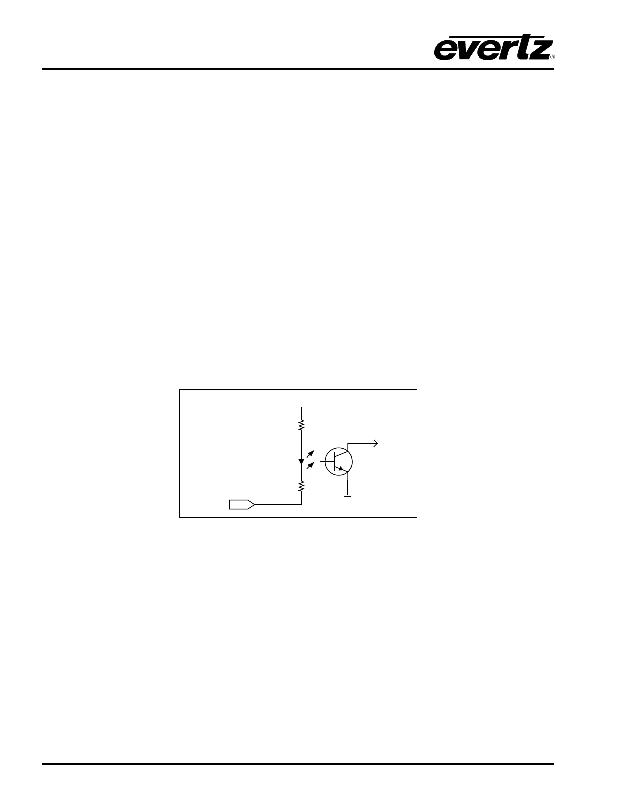
The GPI inputs are considered high if you leave an input floating (not connected) or pull it up to +5
volts. The GPI inputs are considered low when the GPI input is below 0.8 volts. The user can make the
GPIs low simply by connecting the GPI input pins to ground using a button, switch, relay or an open
collector transistor. Figure
2-3 shows the circuitry for each of the GPI input pins.
+ 5 VDC
1 K ohm
to
internal
circuit
10 Ohm
GPI Input
Figure 2-3 : Typical GPI Circuitry
The outputs are internally pulled up to 5 volts. Care must be taken to limit the load to 0.5W so there is
no affect on the power supply source in the frame. Figure
2-4 and Figure 2-5 shows the circuitry for the
GPO1 and GPO2 output pins.