5700ACO
Automatic Changeover
Page 10 Revision 1.0
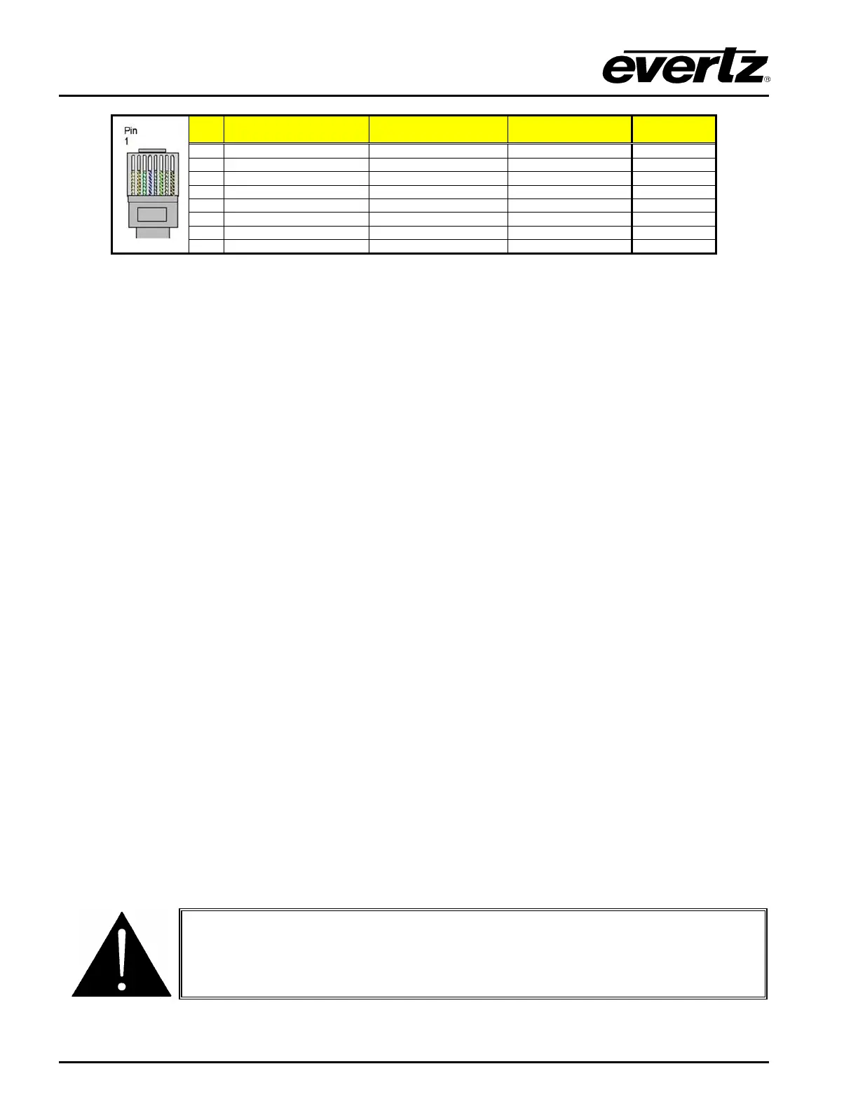
EIA/TIA 568A
AT&T 258A or
EIA/TIA 568B
1000BaseT
Table 2-4 : Standard RJ45 Wiring Colour Codes
Note the following cabling information for this wiring guide:
• Only two pairs (1,2 and 3,6 are used to carry 10 Base-T and 100 Base-T, but all four pairs (1,2 and
3,6 and 4,5 and 7,8) are required by 1000 Base-T.
• 10BaseT and 100BaseT use the same pins; a crossover cable made for one will also work with the
other.
• Pairs may be solid colours and not have a stripe.
• Category 5 cable must use Category 5 rated connectors.
Ethernet switches are used to connect devices on Ethernet networks nowadays. When you have
connected the 5700ACO and set up the IP address you should ‘ping’ the device from your PC to make
sure that it is connected correctly.
2.1.5. Power Connections
LINE: The 5700ACO has redundant universal power supplies operating on 100 to 240VAC,
60 or 50 Hz.
2.2. MOUNTING
The 5700ACO is equipped with rack mounting angles and fits into a standard 19 inch by 1 3/4 inch (483
mm x 45 mm) rack space. The mounting angles may be removed if rack mounting is not desired.
Care must be taken to ensure that the side exhaust vents have a 2” (5cm) clearance to allow for proper
cooling of the unit. The unit may overheat if cables or brackets are blocking the fan exhaust.
2.3. POWER REQUIREMENTS
Power requirements are 100 to 240 volts AC at 50 or 60 Hz. The 5700ACO has redundant universal
power supplies that automatically sense the input voltage. Power should be applied by connecting a
3-wire grounding type power supply cord to each of the power entry modules on the rear panel. The
power cord should be minimum 18 AWG wire size; type SVT marked VW-1, maximum 2.5 m in length.
To reduce the risk of electric shock, grounding of the centre pin of the mains
plug must be maintained.