XRF1/XRF1A 16x16 RF Router Manual
iv Revision 1.2 CONTENTS
8.1.3. RF Specifications: IF ....................................................................................................8-1
8.1.4. LNB Power (LNB option only) ...................................................................................... 8-2
8.1.5. Communication and Control......................................................................................... 8-2
8.1.6. Electrical.......................................................................................................................8-2
8.1.7. Compliance .................................................................................................................. 8-2
8.1.8. Physical........................................................................................................................ 8-2
8.2. SERVICING INSTRUCTIONS.................................................................................................. 8-3
8.2.1. Changing the Fuses ..................................................................................................... 8-3
Figures
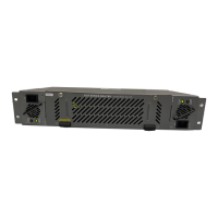
Figure 2-1: XRF1 Rear Panel Layout................................................................................................... 2-1
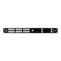
Figure 4-1: Front Panel ........................................................................................................................ 4-1
Figure 4-2: Blank Front Panel .............................................................................................................. 4-1
Figure 4-3: Configuration Menus Structure per Input Channel........................................................... 4-16
Figure 5-1: Panel Lock Operation ......................................................................................................... 5-1
Figure 5-2: Configuration Menu Structure per Input Channel .............................................................. 5-2
Figure 5-3: Configuration Menu Access Operation .............................................................................. 5-4
Figure 5-4: Destination Lock Access Operation – Enabling a Destination Lock .................................. 5-6
Figure 7-1: VistaLINK
®
Configuration Menu for each Router Input....................................................... 7-2
Figure 7-2: VistaLINK
®
Crosspoint Cross Matrix ................................................................................... 7-2
Tables
Table 2-1: Router RS-232 Port Pin Definitions...................................................................................... 2-2
Table 2-2: Router RS-422 Port Pin Definitions...................................................................................... 2-3
Table 4-1: Button Operations for Destination Selection Mode .............................................................. 4-1
Table 4-2: Button Operations for Salvo Selection Mode ....................................................................... 4-2
Table 4-3: Button Operations for Source Selection Mode..................................................................... 4-2
Table 4-4: Button Operations for Configuration Menu Mode................................................................. 4-3
Table 4-5: Button Operations for Configuration Set Mode .................................................................... 4-4
Table 4-6: Overview of Push-Button Operations...................................................................................4-5
Table 4-7: Description of Display Function within XRF1 Modes of Operation...................................... 4-7
Table 4-8: Description of Status Indicator LED Functions................................................................... 4-13
Table 4-9: Configuration Menu Options .............................................................................................. 4-14
Table 4-10: Configure Output Menu Options ...................................................................................... 4-14
Table 4-11: Options Available for ALL INPUTS or Individual Input Channel
as Selected in Configure Output Menu Level 1 ............................................................... 4-14
Table 4-12: Configure Input Menu Options......................................................................................... 4-15
Table 4-13: Options Available for ALL INPUTS or Individual Input Channel
as Selected in Configure Input Menu Level 1 .................................................................. 4-15
Table 4-14: RF Threshold Menu Options............................................................................................ 4-15