XRF1/XRF1A 16x16 RF Router Manual
CONTENTS Revision 1.2 iii
5.3.4. [OUTPUT] Function from Configuration Set Mode....................................................... 5-3
5.4. [MENU] FUNCTION................................................................................................................. 5-3
5.4.1. [MENU] Function from Source and Destination Selection Modes –
Passcode Protection Enabled...................................................................................... 5-3
5.4.2. [MENU] Function from Source and Destination Selection Modes –
Passcode Protection Not Enabled................................................................................ 5-4
5.4.3. [MENU] Function from Configuration Menu Mode or Configuration Set Mode ............ 5-4
5.5. DESTINATION [LOCK] FUNCTION........................................................................................ 5-5
5.5.1. [LOCK] Function........................................................................................................... 5-5
5.6. DESTINATION [PROTECT] FUNCTION................................................................................. 5-6
5.7. [TAKE] FUNCTION ................................................................................................................. 5-6
5.8. [ENTER] FUNCTION ............................................................................................................... 5-7
5.8.1. [ENTER] Function from Destination Selection Mode ................................................... 5-7
5.8.2. [ENTER] Function from Source Selection Mode.......................................................... 5-7
5.8.3. [ENTER] Function from Configuration Menu Mode...................................................... 5-8
5.8.4. [ENTER] Function from Configuration Set Mode ......................................................... 5-8
6. OPERATION..................................................................................................................................... 6-1
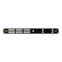
6.1. X-NCP2 ROUTER CONTROL PANEL .................................................................................... 6-1
6.1.1. Connections ................................................................................................................. 6-1
6.1.2. Mounting ...................................................................................................................... 6-1
6.1.3. Specifications............................................................................................................... 6-2
6.1.3.1. Serial I/O (COM 1) ....................................................................................... 6-2
6.1.3.2. Ethernet I/O.................................................................................................. 6-2
6.1.3.3. Electrical....................................................................................................... 6-2
6.1.3.4. Physical........................................................................................................ 6-2
6.1.4. X-NCP2 Configuration Menu........................................................................................ 6-2
6.1.5. Setting the X-NCP2 IP Address ................................................................................... 6-3
6.1.6. Adding XRF1 Router to XNCP2 Control List................................................................ 6-3
6.1.7. Initiating a Control Session with an XRF1.................................................................... 6-3
6.1.8. Terminating a Control Session with an XRF1 .............................................................. 6-4
6.1.8.1. Controlling Crosspoints Using the X-NCP2.................................................. 6-4
6.1.8.2. Example 1: Pushbutton control to switch input 2 to output 5 ...................... 6-4
6.1.8.3. Example 2: Rotary knob control to switch input 2 to output 5..................... 6-4
6.1.9. Control Configuration Items with the X-NCP2.............................................................. 6-5
6.1.10. Panel Lock Button........................................................................................................ 6-5
6.1.11. Lock Button .................................................................................................................. 6-5
6.1.12. Protect Button .............................................................................................................. 6-5
6.1.13. Salvo Select Button...................................................................................................... 6-5
6.1.14. Escape Key.................................................................................................................. 6-5
7. VISTALINK
®
REMOTE MONITORING/CONTROL.......................................................................... 7-1
7.1. WHAT IS VISTALINK
®
?.............................................................................................................. 7-1
7.2. VISTALINK
®
INTERFACE ........................................................................................................ 7-1
8. TECHNICAL DESCRIPTION............................................................................................................ 8-1
8.1. SPECIFICATIONS................................................................................................................... 8-1
8.1.1. SYSTEM ...................................................................................................................... 8-1
8.1.2. RF Specifications: L Band............................................................................................ 8-1