Installation manual
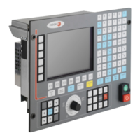
CNC 8035
1.
CNC CONFIGURATION
CNC structure
(SOFT M: V15.3X)
(S
OFT T: V16.3X)
·46·
Connector X3 For probe connection
9-pin normal density SUB-D type female connector.
Up to 2 probes may be connected. There are 2 feedback inputs for each one (5V and 24V).
All shields must only be connected to ground at the CNC end through pin 1 of the connector leaving
the other end free. The wires of the shielded cables cannot be unshielded for more than 75mm (about
3 inches).
Connector X4 For analog spindle connection
15-pin high density SUB-D type female connector.
It admits 1Vpp and differential TTL feedback.
The cable shield must be connected to the metallic hood at each end.
Pin Signal and function
1
2
3
4
5
Chassis
+5 V
PRB1_5
PRB1_24
GND
Shield.
Probe 1. +5 V output for the probe.
Probe 1. 5 V TTL input.
Probe 1. 24 V DC input.
Probe 1. Probe's 0 V input.
6
7
8
9
+5 V
PRB2_5
PRB2_24
GND
Probe 2. +5 V output for the probe.
Probe 2. 5 V TTL input.
Probe 2. 24 V DC input.
Probe 2. Probe's 0 V input.
Pin Signal and function
1
2
3
4
5
6
7
8
A
/ A
B
/ B
I0
/ I0
- - -
- - -
Feedback signals.
9
10
11
12
13
14
15
+5 V
ana_out
GND
GND
- - -
- - -
Chassis
+5 V output for feedback.
Velocity command output.
0 V output for feedback.
0 V output for velocity command.
Shield.

 Loading...