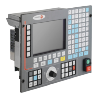
Installation manual
CNC 8035
CNC CONFIGURATION
CNC structure
1.
(SOFT M: V15.3X)
(S
OFT T: V16.3X)
·47·
Connector X5 For electronic handwheel connection
15-pin high density SUB-D type female connector.
It admits differential (double-ended) and non-differential (single-ended) TTL feedback.
The cable must have overall shielding. The rest of the specifications depend on the feedback system
used and the cable length required.
The cable shield must be connected to the metallic hood at each end.
It is highly recommended to run these cables as far as possible from the power cables of the machine.
When using a FAGOR 100P model handwheel, connect it as first handwheel and connect the axis
selecting signal (button) to pin 13.
Connector X6 For Operator Panel connection
26-pin high density SUB-D type female connector.
FAGOR AUTOMATION provides the cable necessary for this connection. This cable has two 26-
pin male connectors of the high density SUB-D type.
Both connectors have a latching system by means of two screws UNC4.40.
It is a straight connection, 1 to 1, 2 to 2, 3 to 3 and so on. The cable hose shield is soldered to the
metal hoods covering both connectors.
Pin Signal and function
1
2
3
4
A1
/A1
B1
/B1
Feedback signals of first handwheel.
5
6
7
8
A2
/A2
B2
/B2
Feedback signals of second handwheel.
9
10
11
12
13
14
15
+5 V
+5 V
GND
GND
100P
- - -
Chassis
Supply output.
Supply output.
Supply output.
Supply output.
Push button of Fagor 100P handwheel.
Shield

 Loading...