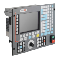
Installation manual
CNC 8035
(SOFT M: V15.3X)
(S
OFT T: V16.3X)
·7·
8.5 Action instruction. .................................................................................................. 306
8.5.1 Binary assignment instructions .......................................................................... 307
8.5.2 Conditional binary action instructions ................................................................ 308
8.5.3 Sequence breaking action instructions.............................................................. 309
8.5.4 Arithmetic action instructions ............................................................................. 310
8.5.5 Logic action instructions .................................................................................... 312
8.5.6 Specific action instructions ................................................................................ 314
CHAPTER 9 CNC-PLC COMMUNICATION
9.1 Auxiliary M, S, T functions ..................................................................................... 318
9.2 Auxiliary M, S, T function transfer.......................................................................... 321
9.2.1 Transferring M, S, T using the AUXEND signal................................................. 322
9.2.2 Transferring the auxiliary (miscellaneous) M functions without the AUXEND signal323
9.3 Displaying messages, errors and screens............................................................. 324
9.4 Access to the PLC from the CNC .......................................................................... 326
9.5 Access to the PLC from a PC, via DNC ................................................................ 327
CHAPTER 10 LOGIC CNC INPUTS AND OUTPUTS
10.1 General logic inputs............................................................................................... 330
10.2 Axis logic inputs..................................................................................................... 338
10.3 Spindle logic inputs................................................................................................ 343
10.4 Key inhibiting logic inputs. ..................................................................................... 348
10.5 Logic inputs of the PLC channel............................................................................ 351
10.6 General logic outputs............................................................................................. 353
10.7 Logic outputs of the axes....................................................................................... 359
10.8 Spindle logic outputs. ............................................................................................ 361
10.9 Logic outputs of key status .................................................................................... 363
CHAPTER 11 ACCESS TO INTERNAL CNC VARIABLES
11.1 Variables associated with tools. ............................................................................ 369
11.2 Variables associated with zero offsets. ................................................................. 373
11.3 Variables associated with machine parameters .................................................... 374
11.4 Variables associated with work zones................................................................... 375
11.5 Variables associated with feedrates ...................................................................... 377
11.6 Variables associated with coordinates .................................................................. 379
11.7 Variables associated with electronic handwheels ................................................. 381
11.8 Variables associated with feedback ...................................................................... 383
11.9 Variables associated with the main spindle........................................................... 383
11.10 Variables associated with local and global parameters......................................... 386
11.11 Operating-mode related variables ......................................................................... 387
11.12 Other variables ...................................................................................................... 389
CHAPTER 12 AXES CONTROLLED FROM THE PLC
12.1 PLC execution channel.......................................................................................... 398
12.1.1 Considerations................................................................................................... 399
12.1.2 Blocks which can be executed from the PLC .................................................... 401
12.1.3 Control of the PLC program from the CNC........................................................ 405
12.2 Action CNCEX1 ..................................................................................................... 407
CHAPTER 13 PLC PROGRAMMING EXAMPLE
13.1 Definition of symbols (mnemonics)........................................................................ 410
13.2 First cycle module.................................................................................................. 412
13.3 Main module. ......................................................................................................... 413

 Loading...