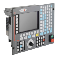
Installation manual
CNC 8035
(SOFT M: V15.3X)
(S
OFT T: V16.3X)
·6·
5.5 Axis adjustment ..................................................................................................... 203
5.5.1 Drive setting....................................................................................................... 204
5.5.2 Gain setting ....................................................................................................... 205
5.5.3 Proportional gain setting.................................................................................... 206
5.5.4 Feed-forward gain setting.................................................................................. 207
5.5.5 Derivative (AC-forward) gain setting.................................................................. 208
5.5.6 Leadscrew backlash compensation................................................................... 209
5.5.7 Leadscrew error compensation ......................................................................... 210
5.6 Reference systems................................................................................................ 212
5.6.1 Home search ..................................................................................................... 213
5.6.2 Setting on systems without distance-coded feedback....................................... 216
5.6.3 Setting on systems with distance-coded feedback............................................ 218
5.6.4 Axis travel limits (software limits)....................................................................... 219
5.7 Unidirectional approach......................................................................................... 220
5.8 Auxiliary M, S, T function transfer.......................................................................... 221
5.8.1 Transferring M, S, T using the AUXEND signal................................................. 223
5.8.2 Transferring the auxiliary (miscellaneous) M functions without the AUXEND signal224
5.9 Spindle .................................................................................................................. 225
5.9.1 Spindle types ..................................................................................................... 225
5.9.2 Spindle speed (S) control .................................................................................. 226
5.9.3 Spindle gear change.......................................................................................... 228
5.9.4 Spindle in closed loop........................................................................................ 230
5.10 Treatment of emergency signals ........................................................................... 236
5.11 Digital CAN servo .................................................................................................. 239
5.11.1 Communications channel .................................................................................. 239
5.12 Fagor handwheels: HBA, HBE and LGB............................................................... 242
5.13 Machine safety related functions........................................................................... 246
5.13.1 Maximum machining spindle speed .................................................................. 246
5.13.2 Cycle start disabled when hardware errors occur. ............................................ 248
5.14 Tool magazine....................................................................................................... 249
5.14.1 Tool change via PLC ......................................................................................... 249
5.14.2 Tool change management................................................................................. 250
5.15 Gear ratio management on axes and spindle........................................................ 251
5.15.1 Example of axes: outside feedback without gear box ....................................... 252
5.15.2 Example of axes: encoder at the motor............................................................. 255
5.15.3 Example of axes: outside feedback with gear box ............................................ 256
5.15.4 Example of spindle: external encoder without gear box .................................... 258
5.15.5 Example of spindle: encoder at the motor ......................................................... 260
5.15.6 Example of spindle: external encoder with gear box ......................................... 262
CHAPTER 6 PLC RESOURCES
6.1 Inputs..................................................................................................................... 265
6.2 Outputs.................................................................................................................. 266
6.3 Marks..................................................................................................................... 267
6.4 Registers ............................................................................................................... 269
6.5 Timers ................................................................................................................... 270
6.5.1 Monostable mode. TG1 input ............................................................................ 273
6.5.2 Delayed activation mode. TG2 input ................................................................. 275
6.5.3 Delayed deactivation mode. TG3 input ............................................................. 277
6.5.4 Signal limiting mode. TG4 Input ........................................................................ 279
6.6 Counters................................................................................................................ 281
6.6.1 Operating mode of a counter............................................................................. 284
CHAPTER 7 INTRODUCTION TO THE PLC
7.1 PLC resources....................................................................................................... 286
7.2 PLC program execution......................................................................................... 287
7.3 Loop time............................................................................................................... 290
7.4 Modular structure of the program .......................................................................... 291
7.4.1 First cycle module (CY1) ................................................................................... 292
7.4.2 Main module (PRG)........................................................................................... 293
7.4.3 Periodic execution module (PE t) ...................................................................... 294
7.4.4 Priority of execution of the PLC modules .......................................................... 295
CHAPTER 8 PLC PROGRAMMING
8.1 Module structure.................................................................................................... 298
8.2 Directing instructions ............................................................................................. 299
8.3 Consulting instructions .......................................................................................... 303
8.4 Operators and symbols ......................................................................................... 305

 Loading...