TOR
25
cod. 3542B750 - Rev 05 - 07/2022
EN
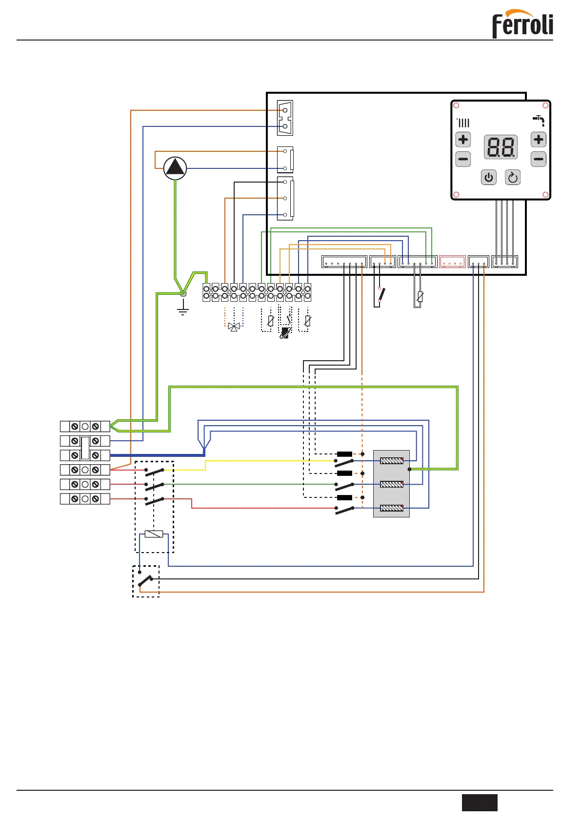
4.6 WIRING DIAGRAM
4.6.1 Wiring diagrams for models 6, 9 and 12
g. 16 - For Models 6 - 9 - 12
Key
2 Safety thermostat (manual reset)
3 Heating temperature sensor
4 Solid-state relay
6 Circuit breaker
32 Central heating pump
95 Diverting valve (optional)
114 Water pressure switch
138 Outside temperature sensor (optional)
139 Room unit (optional)
155 Storage tank sensor (optional)
ATTENTION: Before connecting the room thermostat or the remote timer control, remove the jumper from terminals 9-10
on the terminal block.