TOR
51
cod. 3542B750 - Rev 05 - 07/2022
RO
TOR
25
cod. 3542B750 - Rev 00 - 05/2022
EN
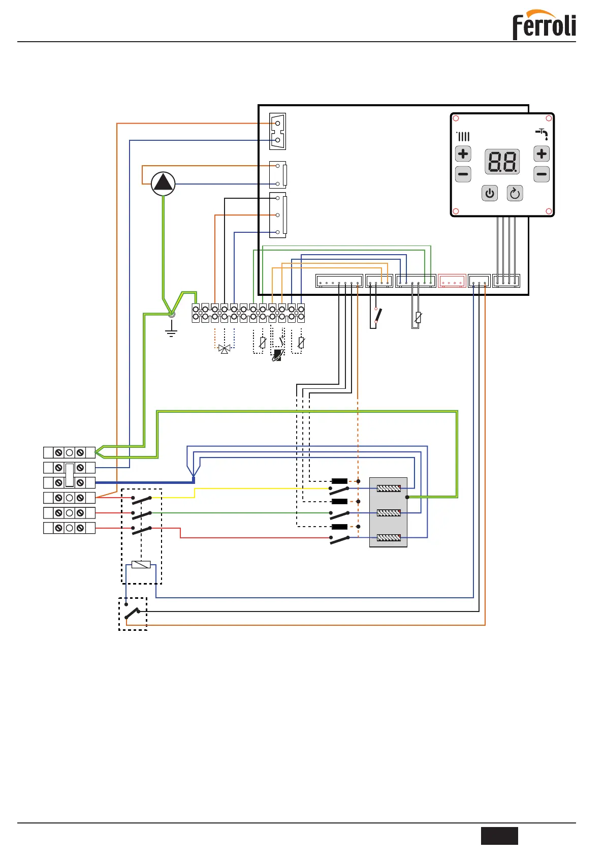
4.6 WIRING DIAGRAM
4.6.1
- For Models 6 - 9 - 12
Key
2 Safety thermostat (manual reset)
3 Heating temperature sensor
4 Solid-state relay
6 Circuit breaker
32 Central heating pump
95 Diverting valve (optional)
114 Water pressure switch
138 Outside temperature sensor (optional)
139 Room unit (optional)
155 Storage tank sensor (optional)
Before connecting the room thermostat or the remote timer control, remove the jumper from terminals 9-10
on the terminal block.
4.6. Schema circuitului centralei electrice
4.6.1. Diagrama electrica pentru modelele 6, 9 și 12
Fig. 17 - Pentru modelele 6 - 9 - 12
ATENTIE : Inaintedeconectareatermostatuluidecameraindepartatipunteaexistentainrigletele9-10
Legenda
2 Termostatdesiguranta
3 Senzortemperaturaincalzire
4 Relee
6 Sigurantaautomata
32 Pompacirculatie
95 Vana cu 3 cai
114 Presostatdeapa
138 Senzordeexterior
139 Termostatambient
155 Senzoracm
4.6 SCHEMACIRCUITULUICENTRALEIELECTRICE
4.6.1 Diagramaelectricapentrumodelele6,9și12