3. Product description
28 Festo.P.BE-CMMS-ST-G2-HW-EN 1008NH
The following signals can be evaluated:
• A/B tracking signals
• CLK/DIR – pulse/direction
• CW/CCW pulse
Input: Processing of pulse-direction signals 24 V DC [X1]
• CLK/DIR – pulse/direction
• CW/CCW pulse
24 V DC pulse-direction signals are carried out via X1 DIN2 and DIN3.
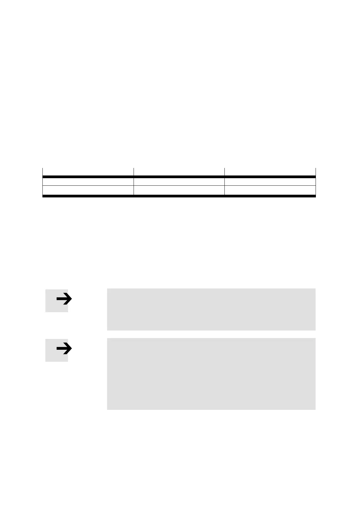
Cycle rate pulse-direction signals
Voltage Input Cycle rate
5 V [X10] 150 kHz
24 V [X1]
up to 20 kHz
Table 3.3 Maximum input frequency
Activation of synchronisation
Synchronisation can be set in various ways.
• With the FCT parameterisation software, through selection of the control interface
“Synchronisation” on the “Application data” page in the “Operating modes selection”
tab
• Via [X1] (digital I/O interface) through selection of mode 3
Note
With setting of synchronisation via FCT, the controller only reacts
via the synchronisation interface. All other functions of the
positioning operating mode are no longer available.
Note
After the change of configuration via FCT, the changed
configurations must be loaded into the motor controller using the
“Download” buttons and saved permanently with the “Save”
button.
With a “Reset” (or switching off and back on) of the motor
controller, the new configuration is activated.
To ensure flexibility of the controller, synchronisation should be switched on over the I/O
interface.

 Loading...


