7 Modification
Festo – MPAL-VI-EN – 2017-07a – English 79
7.3 Replacing or extending the sub-base, supply module, and/or repla
cing the right end plate
7.3.1 Maximum number of sub-bases
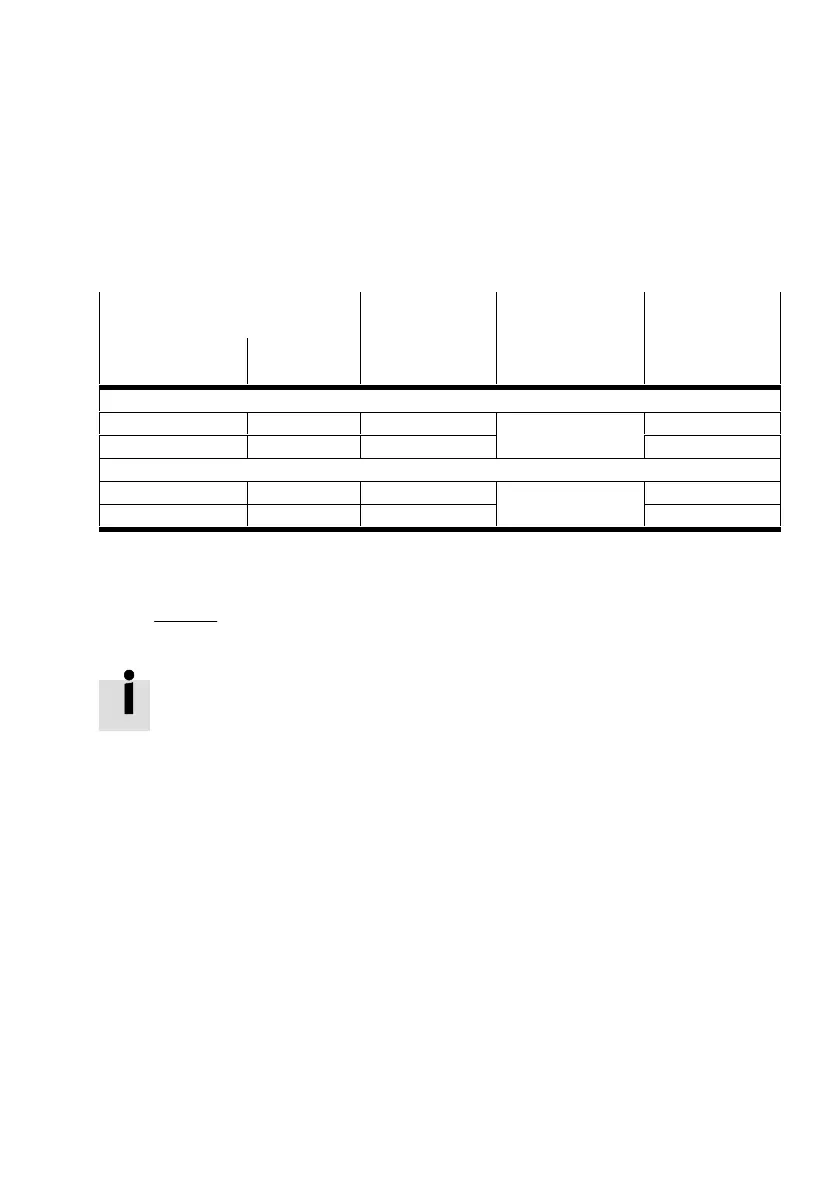
If equipped exclusively with one size and valves with the same number of solenoid coils, this will result
in the following maximum number of sub-bases Xmax:
Electrical interlinking of the sub-base Solenoid coils
that can be activ
ated per valve po
sition n1
Valve positions per
sub-base n2
Maximum num
ber of sub-bases
X
max
Type Housing colour
Individual electrical interlinking module
VMPAL-EVAP-...-1 Grey 1 1 32
VMPAL-EVAP-...-2 Black 2 16
4-way electrical interlinking module
VMPAL-EVAP-...-1-4 Grey 1 4 8
VMPAL-EVAP-...-2-4 Black 2 4
Tab. 7.3 Maximum number of sub-bases
With 32 actuated solenoid coils, the maximum number of sub-bases X
max
can be calculated as follows:
X
max
+
32
ǒ
n
1
n
2
Ǔ
Valve terminal with CPX terminal:
After converting or extending the valve terminal, adjust the number of output ad
dresses occupied by the pneumatic components using the rotary switch on the pneu
matic interface èChap. 2.6.8.
If a sufficiently large address space was reserved for the extension beforehand, make
no changes to the switch setting.
Modifications to the configuration will not become effective until the operating
voltage is switched on again.
 Loading...