64 ECS Series Manual — P/N LS10262-001FK-E:A 3/3/2021
Device Installation Addressing SBUS Devices
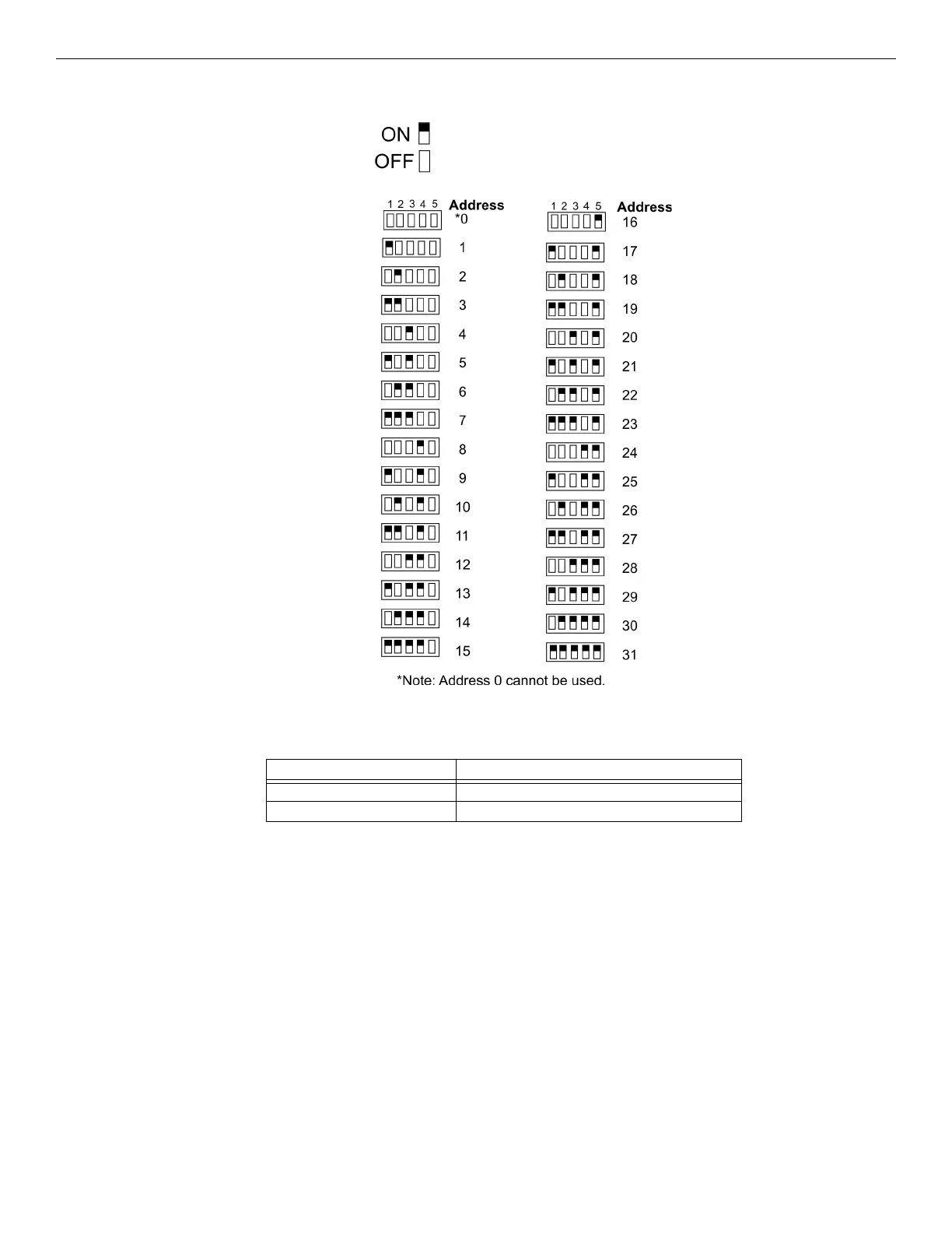
Figure 4.67 shows all possible DIP switch positions and their correlation to a numerical ID. For example, to select ID 2, place DIP switch 2
in the up position.
Figure 4.67 Possible Module Addresses
More information regarding ECS operations, Please refer to the ECS section of the FACP’s installation manual.
ECS Series Model Number FACP Installation Manual
FCP-300ECS LS10145-002FK-E
FCP-2100ECS LS10143-002FK-E